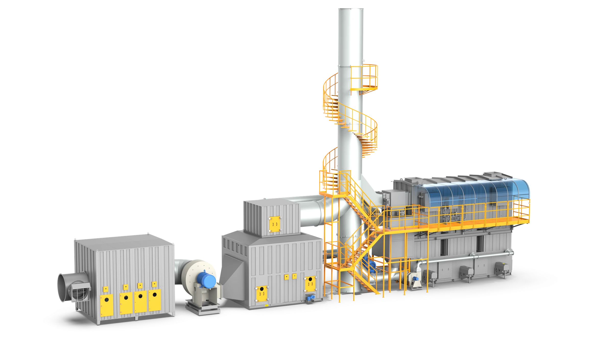
200,000 m³/h Zeolite Drum Concentrator & 3-Bed RTO System
CIMC Vehicles (Jiangmen) Co., Ltd. | Heavy-Duty Tanker & Semi-Trailer Coating Facility
Sub-Micron Zinc Dust & 200,000 m³/h Paint Exhaust — Tamed with Auto-Thermal RTO
CIMC Vehicles (Jiangmen) Co., Ltd., a flagship manufacturing subsidiary of CIMC Vehicles (Group) Co., Ltd. (the world’s foremost semi-trailer and specialized transport tanker builder, listed HKEX: 1839 / SZSE: 301039), embarked on an environmental upgrade across its primary coating workshops. The facility operates 3 manual spray booths and 2 curing ovens for concrete mixers, bulk powder tankers, and aluminum liquid tankers, generating a combined peak exhaust airflow of 200,000 m³/h (117,600 CFM).
The project presented an acute technical hurdle: the application of heavy-duty Kansai epoxy zinc-rich primer produces fine overspray with sub-micron (<1 μm) zinc aerosol particles. Conventional pocket filters allow fine zinc dust to penetrate, which rapidly blinds zeolite adsorption channels and coats ceramic thermal media. Furthermore, volatile aromatic and ketone solvents (toluene, xylene, PGME, MIBK, isopropanol) produce non-methane hydrocarbon (NMHC) emissions up to 800 mgC/m³ (160 kg/h).
FluxFine engineered a complete turnkey solution integrating twin 100,000 m³/h 5-stage dry filter houses (up to H11 HEPA), a 200,000 m³/h cylindrical zeolite drum concentrator (delivering up to 28.6:1 concentration), and a high-thermal-efficiency30,000 m³/h 3-bed Regenerative Thermal Oxidizer (RTO).
5-stage G4+F5+F7+F9+H11 filtration protects downstream zeolite molecular sieves from metallic fouling.
Self-sustaining oxidation at ≥465 mg/m³; peak 800 mg/m³ yields 1,984 kW heat with zero fuel consumed.
200,000 m³/h stream concentrated down to 7,000–30,000 m³/h, reducing required oxidizer footprint by 85%.
Auto-thermal self-sustaining operation with zero auxiliary fuel required during normal production across all operating booths.
Engineered 4-Stage Treatment Train
From spray booth capture to high-temperature thermal destruction, every stage was dimensioned to prevent particulate blinding, accommodate severe concentration swings, and capture 95% of process thermal energy.
5-Stage HEPA Filtration
Twin 100,000 m³/h houses cascade from G4/F5 through F7/F9 to H11 HEPA, capturing ≥99.9% of sub-micron zinc dust (<1 μm) from Kansai zinc-rich primer.
Zeolite Drum Adsorption
Horizontal cylindrical drum design eliminates face-seal wear. Hydrophobic molecular sieve adsorbs aromatics, esters, and ketones at 90%–95% efficiency.
Desorption Loop
Controlled hot-air stream desorbs captured VOCs into a compact rich stream (7,000 to 30,000 Nm³/h), safely maintaining concentration below 6,000 mg/m³ LEL limit.
3-Bed RTO Destruction
Monolithic honeycomb ceramics recover 95% of thermal energy. 877°C–945°C oxidation destroys hydrocarbons into clean CO₂ and H₂O with zero auxiliary fuel.
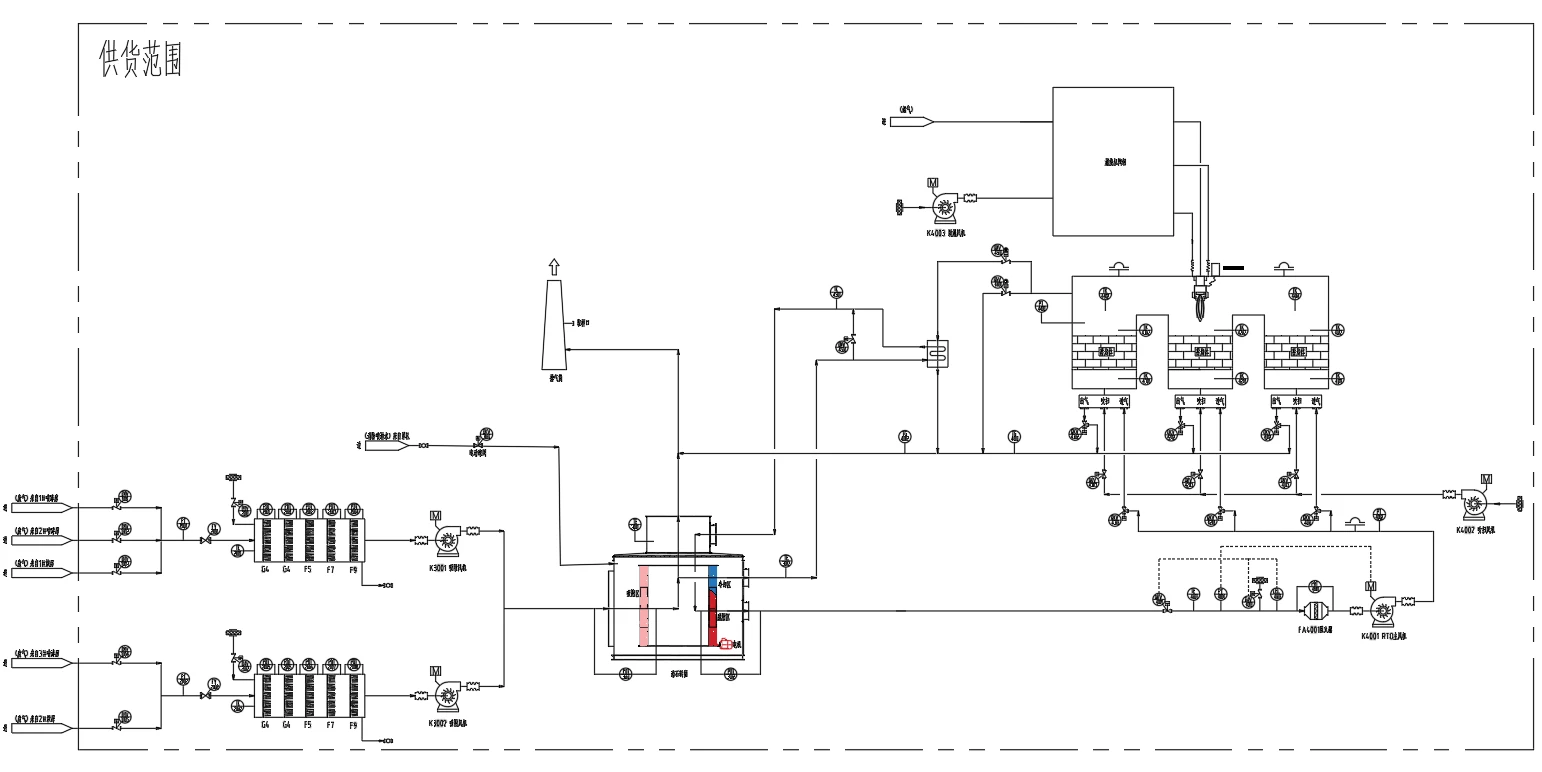
Engineering P&ID System Diagram
Full process flow showing 3 spray booths, 2 curing ovens, twin filter houses, zeolite drum, and 3-bed RTO train.
Tri-Scenario Thermal Balance Matrix
Because spray coating involves dynamic shift cycles, FluxFine modeled system thermodynamics across 3 operating conditions. At concentrations ≥465 mg/m³, the system achieves 100% self-sustaining auto-thermal oxidation.
| Parameter / Condition | Scenario 1: Low-Load Idling | Scenario 2: Nominal Production | Scenario 3: Peak Dual-Booth Spraying |
|---|---|---|---|
| Adsorption Treatment Volume | 200,000 Nm³/h (117,600 CFM) | 200,000 Nm³/h (117,600 CFM) | 200,000 Nm³/h (117,600 CFM) |
| Inlet VOC Concentration | 150 mg/m³ | 465 mg/m³ | 800 mgC/m³ (Peak) |
| Zeolite Drum Removal Efficiency | 90.0% | 90.0% | 94.0% – 95.0% |
| Desorption Airflow & Ratio | 7,000 Nm³/h (28.6 : 1) | 24,000 Nm³/h (8.3 : 1) | 30,000 Nm³/h (6.7 : 1) |
| RTO Inlet VOC Level | 3,871 mg/m³ (<9% LEL) | 3,530 mg/m³ (<8% LEL) | 5,057 mg/m³ (<11.2% LEL) |
| Combustion Chamber Temperature | 892°C (1,638°F) | 877°C (1,610°F) | 945°C (1,733°F) |
| Exothermic Heat Generated | 354 kW | 1,108 kW | 1,984 kW |
| Thermal Self-Balance State | Thermal Neutral (0 kW surplus) | Self-Sustaining (0 kW surplus) | +544 kW Net Surplus Heat |
| Auxiliary Fuel Consumed | Zero (During steady run) | Zero (Self-Sustaining) | Zero (+544 kW Net Surplus Heat Available) |
At standard production solvent concentrations (800 mgC/m³), the 3-bed RTO achieves continuous self-sustaining exothermic combustion, generating 544 kW of net surplus heat with zero auxiliary fuel consumption.
Twin main boost fans (184.8 kW) and RTO draft fan (63 kW) feature real-time static pressure feedback control, maintaining consistent negative booth pressure and preventing fugitive spray leaks.
5-stage filtration with terminal H11 HEPA captures sub-micron zinc overspray down to 0.3 μm, completely preventing micropore fouling and ensuring 10+ year longevity for the zeolite concentrator.
Hydrophobic Zeolite vs. Activated Carbon: Adsorption Isotherms & Dynamic Breakthrough
Why hydrophobic aluminosilicate zeolite was selected over conventional activated carbon for CIMC’s 200,000 m³/h paint exhaust: temperature resilience, non-combustibility, and repeatable multi-cycle desorption recovery without pore collapse.
Zeolite Molecular Sieve vs. Activated Carbon
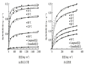
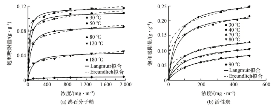
Experimental equilibrium isotherms fitted with Langmuir and Freundlich models demonstrate fundamental thermodynamic differences between the two media:
- High Low-Concentration Affinity: Hydrophobic zeolite exhibits a steep initial isotherm slope, maintaining robust capture capacity (0.10–0.12 g/g) even at dilute VOC concentrations (<500 mg/m³).
- Thermal Resilience vs. Carbon Decay: Activated carbon’s adsorption capacity collapses dramatically as temperature exceeds 50°C. Zeolite maintains high saturation capacity up to 80°C–120°C, and completely desorbs at 180°C–220°C.
- Fire Safety & Moisture Immunity: Inorganic aluminosilicate crystalline matrix is non-flammable (A1 fire rating) and rejects water molecules at <80% RH, preventing carbon bed runaway fires.
Multi-Cycle Adsorption Breakthrough Curves
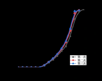
Dynamic breakthrough experiments conducted across three consecutive adsorption–desorption cycles validate process stability under industrial operational stresses:
- Stable 10–12 Hour Breakthrough Point: Zero detectable VOC slip occurs during the initial 10 hours of continuous operation. Breakthrough onset ($C/C_0 > 5\%$) begins synchronously at 12 hours across all cycles.
- Identical Multi-Cycle Trajectories: Breakthrough curves for Cycle 1 (black), Cycle 2 (red), and Cycle 3 (blue) virtually overlap, demonstrating 100% desorption regeneration efficiency with zero residual solvent accumulation.
- Drum Continuous Rotation Safety Margin: In real production, the cylindrical drum rotates continuously with a 40–60 minute cycle, operating far below the 10-hour breakthrough threshold and ensuring ≥94% capture efficiency.
Core Equipment Engineering & Metallurgy
Engineered for 24/7 continuous industrial reliability with redundant explosion safety systems, corrosion-resistant metallurgy, and high-efficiency thermal recovery.
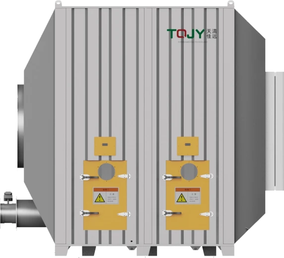
Cylindrical Zeolite Drum
- Radial Geometry: Horizontal cylinder eliminates axial friction wear inherent to vertical disc wheels.
- Zero Seal Deterioration: Engineered air-cushioned perimeter seals prevent bypass leakage over 50,000 operating hours.
- Hydrophobic Sieve: Resists moisture up to 80% RH while maintaining 95% hydrocarbon capture.
3-Bed Regenerative Thermal Oxidizer
- Zero-Slip Purge Cycle: Dedicated purge bed eliminates transient unburned hydrocarbon slip during poppet valve switches.
- 95% Thermal Efficiency: High-density honeycomb ceramic structured monoliths recover almost all process heat.
- Heavy Ceramic Insulation: 250mm ceramic fiber modules maintain casing exterior temperature below 50°C.
Siemens PLC & SCADA Architecture
- Multi-Tier Control: Field manual, remote manual, and fully automated PLC supervisory loops prevent unauthorized setpoint overrides.
- Dual-Channel LEL Interlocks: Continuous FID/LEL analyzers trigger pneumatic fresh-air dilution at 25% LEL threshold.
- Cloud Telemetry App: Real-time remote monitoring of fan frequencies, valve positions, temperatures, and automated SMS/email alerts.
PLC Supervisory Control & Safety Interlock Architecture
Three-stage closed-loop automation: Continuous Field Inputs → Siemens S7 Processing → Real-Time Alarms & Fail-Safe Interlocks
High-frequency 1-second operational telemetry, long-term trend logging, and temperature/pressure compliance audit trails.
PID-regulated VFD airflow balancing, auto-thermal fuel ratio modulation, and sub-second poppet valve sequencing.
Equipment in This Project
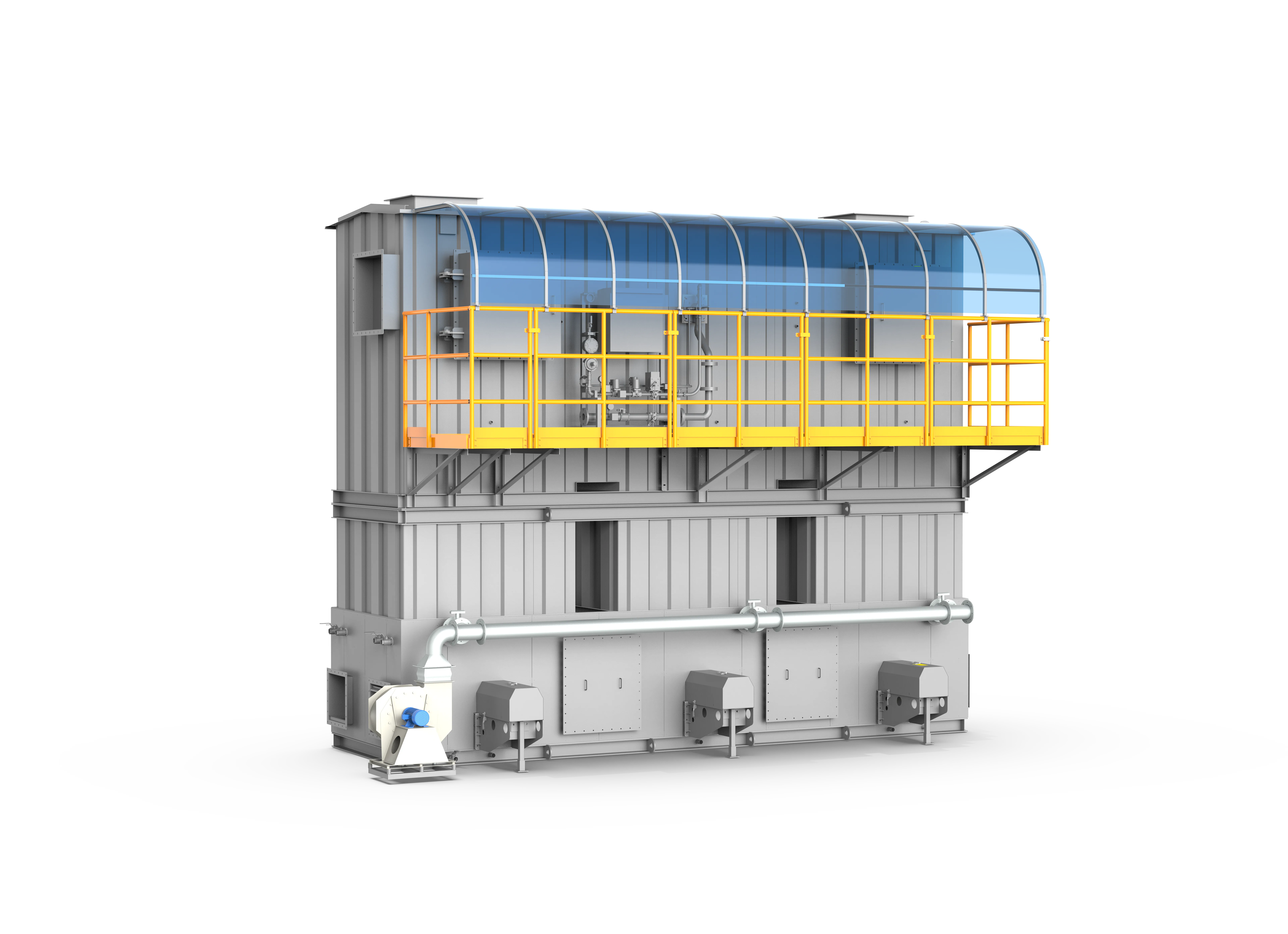
Three-Tower RTO
A premier-grade industrial VOC thermal abatement system that achieves >=99% VOC destruction efficiency and >=95% thermal energy recovery through a classic three-bed alternating heat-exchange and purge process.
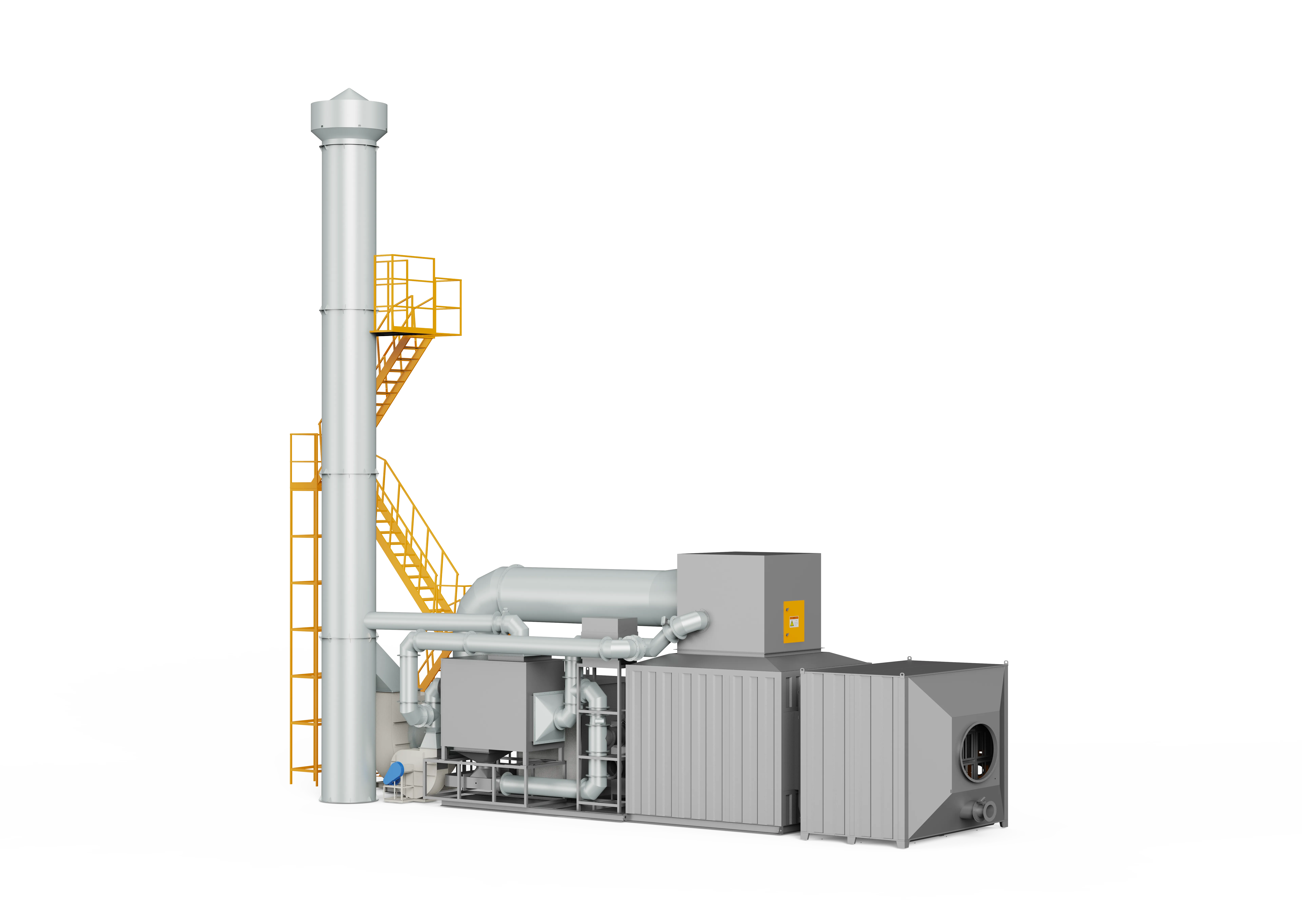
Zeolite Rotor
A high-efficiency VOC pre-treatment and concentration system utilizing advanced hydrophobic zeolite molecular sieves to continuously adsorb, desorb, and enrich large-airflow, low-concentration organic exhaust gases, reducing downstream thermal destruction energy consumption by 40% to over 50%.
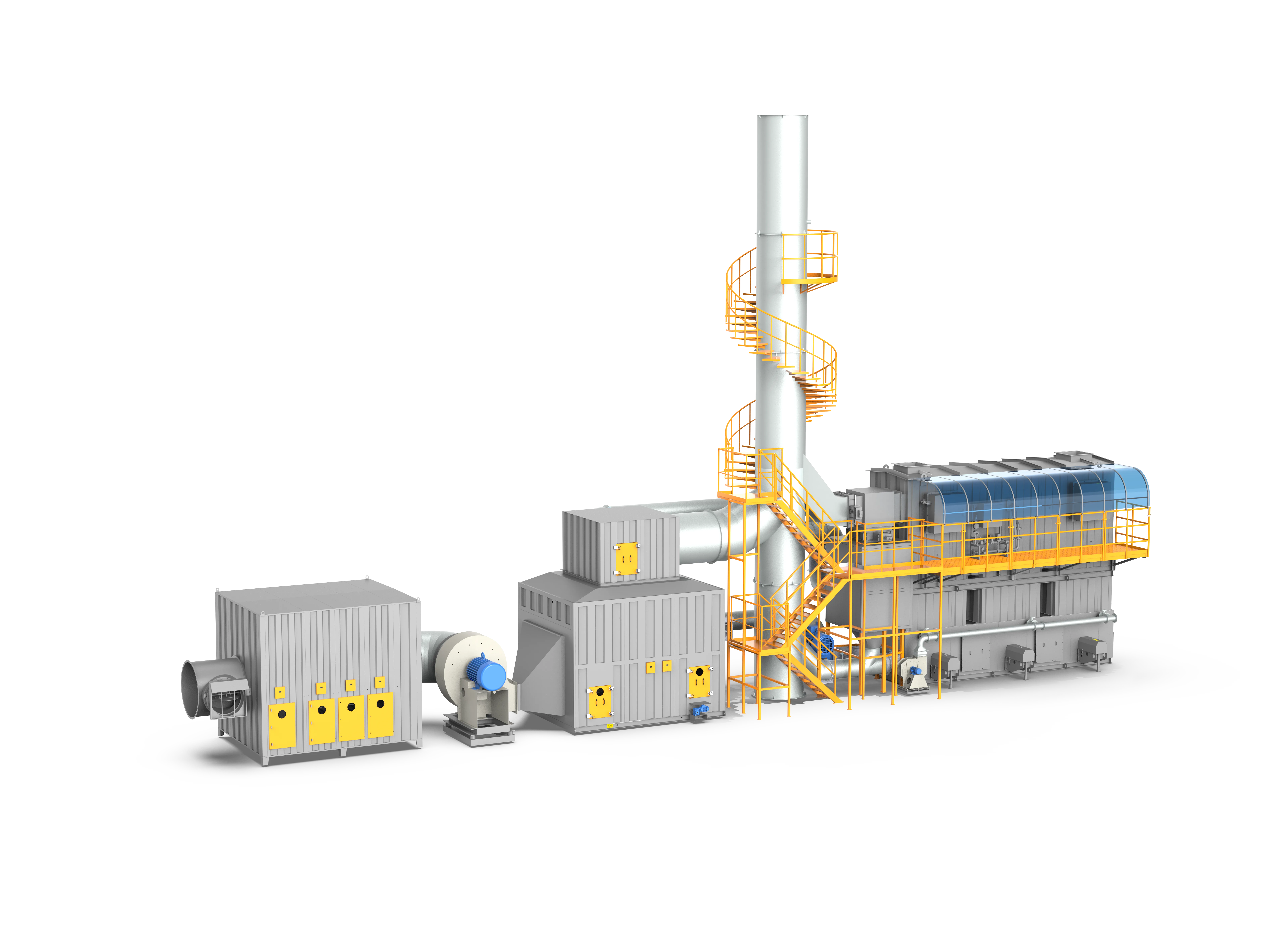
Rotor + 3-Tower RTO
The premier system for large-airflow, low-concentration VOC emissions, combining a hydrophobic zeolite rotor for 10-40x gas enrichment with a mature three-tower RTO for complete destructive oxidation, cutting energy costs by 40%-60%.
Evaluate This System Architecture for Your Paint Facility
Whether you manufacture specialized commercial tankers, automotive body panels, or heavy structural equipment, our environmental engineering team delivers customized airflow diagnostics, thermal balance calculations, and turnkey compliance guarantees within 24 hours.