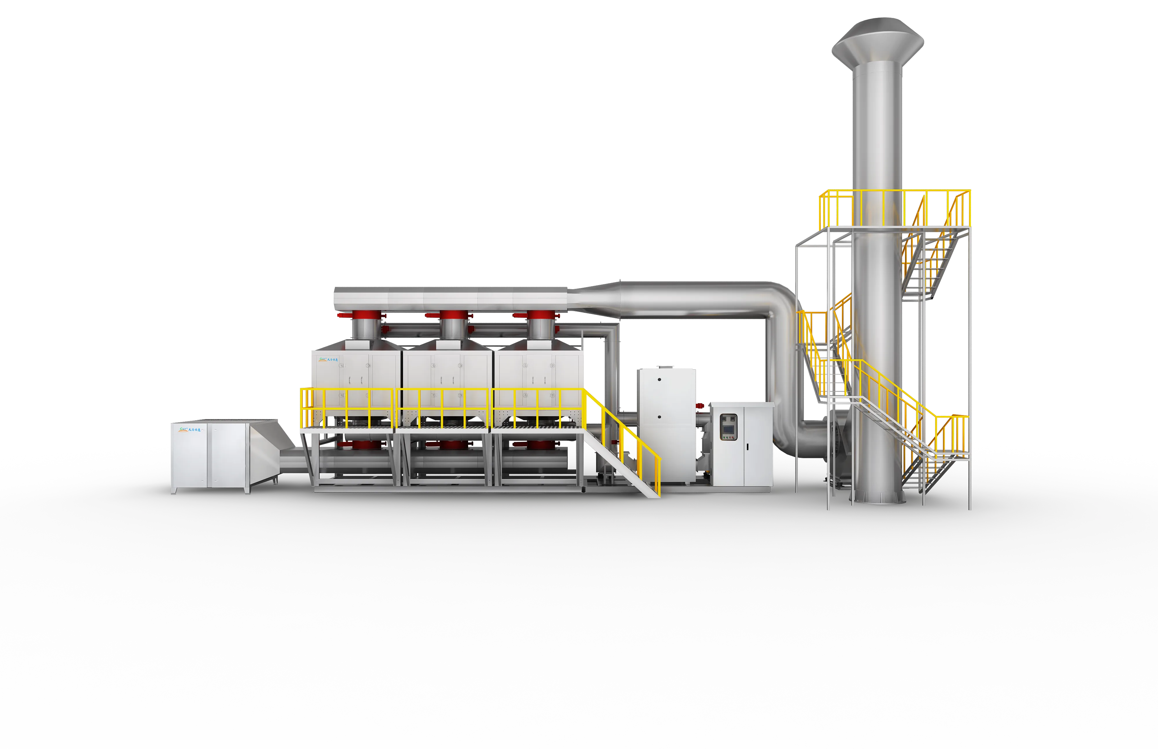
Activated Carbon Adsorption Desorption & Catalytic Combustion Integrated Machine
An exceptionally economical VOC abatement package integrating multi-bed activated carbon adsorption with hot-air thermal regeneration and low-temperature catalytic oxidation (CO) for small-scale, intermittent emissions.
Designed around actual process conditions
For small-to-medium enterprises operating on intermittent schedules with restricted capital budgets, the FluxFine Activated Carbon Adsorption Desorption & Catalytic Combustion (CO) Integrated Machine delivers a perfect balance of cost and compliance. By utilizing premium, highly porous activated carbon beds to capture VOCs and cycling them through on-site hot-air thermal regeneration, the system avoids recurring carbon replacement costs. The desorbed high-concentration VOCs are destroyed in a compact catalytic oxidizer at 280-350°C, returning heat to the desorption loop and achieving highly economical compliance.
Activated Carbon CO Skid / Carbon Concentrator with Catalytic Oxidizer / Economic Carbon Recovery and Destruction
Meets conventional municipal environmental and discharge standards with ease.
Ensures low-temperature, flameless, and safe organic destruction.
Minimizes required plant floor space, supporting convenient outdoor or rooftop placements.
Operating references and configuration choices
These reference values and modules clarify the scope we evaluate. They are not a substitute for a process-data review or final proposal.
| Engineering reference | Value | How to read it |
|---|---|---|
| Application pattern | Low concentration / intermittent | Source application guidance; actual suitability follows mass loading and cycle study. |
| Catalytic oxidation range | 280–350°C | Source reference for the desorbed stream. |
| Removal reference | ≥90% | Source reference for conventional VOC applications; project-specific. |
Typical modules considered
- Pre-filter and cooling/conditioning where required
- Carbon adsorption bed(s) with temperature monitoring
- Saturation detection and hot-air desorption system
- Catalytic oxidation chamber and heat-reuse loop
- Fire, anti-static and emergency isolation provisions
Project-specific selection notes
- Size carbon inventory from solvent mass loading and expected adsorption/desorption cycle, not airflow alone.
- Treat high humidity, oil, dust and temperature as up-front design constraints.
- Confirm safe desorption, catalyst compatibility and response to production stoppages.
Carbon + CO vs. solvent recovery
Carbon + CO destroys the desorbed organic stream. Steam desorption and condensation recovery may be evaluated when solvent value, purity, utilities and liquid handling justify recovery. Both need detailed safety and chemistry review.
- The VOCs equipment source identifies small-to-medium, intermittent coating, screen-printing, ink, plastics and metalworking duties as candidate contexts.
- Actual removal efficiency, carbon life and operating cost are project-specific.
What we review before specifying Carbon + CO
A product name is a starting point, not a final design. These inputs define pretreatment, materials, controls, equipment size and scope boundaries.
Project data to provide
- VOC species and catalyst-compatibility screening
- Airflow, concentration profile and desired operating cycle
- Sulfur, chlorine, silicon, phosphorus, heavy-metal and aerosol content
- Pretreatment condition and available utilities
- Required emission limit and installation footprint
Typical engineered scope
- Filtration and conditioning matched to catalyst protection
- Catalyst reactor, heater and heat-exchanger configuration
- Optional zeolite or carbon adsorption/concentration stage
- Temperature, pressure and fan controls with safety permissives
- Access for catalyst inspection and planned maintenance
Safety and controls
- Catalyst poison screening is a prerequisite, not an optional upgrade.
- Dust, oil and sticky aerosol must be controlled upstream to protect adsorption media and catalyst surfaces.
- Temperature management and interlocks are configured for the selected catalyst and fuel/heat source.
- No public page should promise a fixed removal rate without the actual gas composition and design basis.
How it works
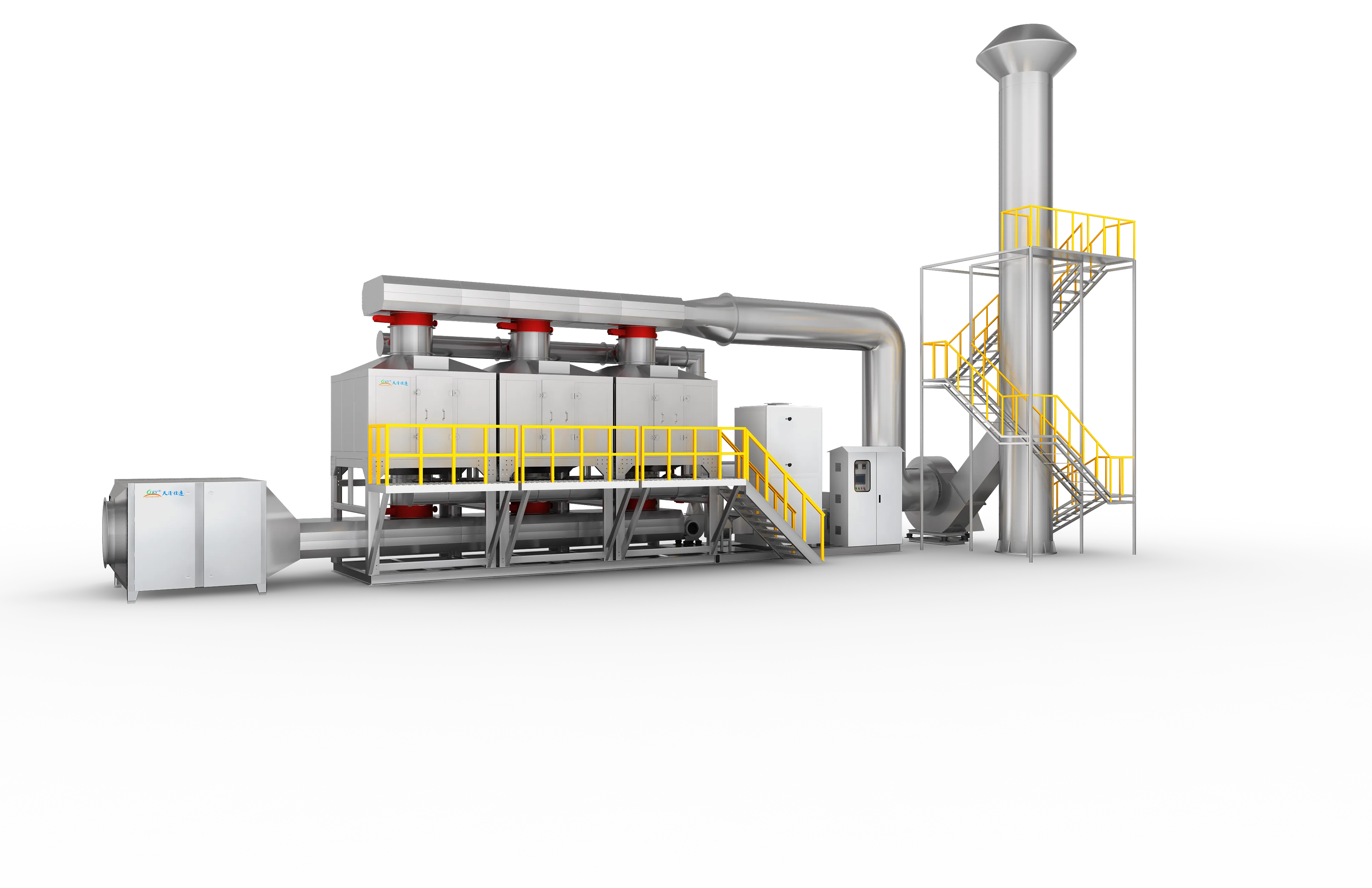
Raw solvent-laden air undergoes primary dry filtration to trap particulates, then passes through a multi-bed activated carbon chamber. The highly porous carbon captures the organic molecules, allowing clean air to vent. As a carbon bed approaches saturation, the system automatically switches process air to a secondary parallel bed and starts regeneration on the saturated bed. High-temperature hot air is introduced to thermally desorb the VOCs, creating a high-concentration, low-airflow gas stream. This stream is preheated to 280-300°C and routed to the catalytic combustion chamber. Over a noble metal catalyst, the VOCs oxidize into CO2 and H2O at 280-350°C. Internal heat exchangers recover the reaction heat to maintain the desorption loop, minimizing electric or gas utility consumption.
- 01Inlet air conditioning via primary dry filtration to trap dust and paint aerosols.
- 02Physical adsorption of VOCs at ambient temperature across highly porous activated carbon beds.
- 03Venting of purified, compliant process air to the exhaust stack.
- 04Automatic cycling of process air to an adjacent parallel carbon bed upon saturation detection.
- 05Thermal desorption of the saturated bed using hot air sweeping to yield a highly concentrated stream.
- 06Preheating of concentrated gas and introduction into the noble-metal catalytic oxidizer.
- 07Flameless catalytic oxidation at 280-350°C, converting organic solvents into CO2 and H2O with >=90% efficiency.
- 08Recycling of catalytic reaction heat to supply the hot air desorption loop.
- Small-to-medium airflows (<30,000 m³/h), low concentrations (<300 mg/m³), and intermittent operations.
- Budget-sensitive facilities requiring reliable VOC compliance without major infrastructure investments.
- Sectors including small paint booths, silk-screen printing shops, hardware processing, plastic extruders, and adhesive assembly.
- Plants with highly periodic operating shifts (e.g., 8-12 hours per day).
- Strictly prohibit high-temperature, high-humidity, or highly oily process streams; high moisture will cause carbon compaction and permanent loss of adsorption capacity.
- Avoid introducing chlorine, sulfur, heavy metals, or silicone compounds to prevent permanent poisoning of the noble metal catalyst.
- Adsorption saturation levels must be systematically monitored; delayed regeneration will lead to organic breakthroughs and compliance violations.
- Incorporate strict fire-prevention modules, high-temperature alarms, and automatic water-sprinkler systems within the carbon beds to prevent thermal runaways.
Typical pollutants
- Benzene
- Toluene
- Xylene
- Ethyl Acetate
- Butyl Acetate
- Isopropanol
- Ethanol
- Mixed Aliphatic Hydrocarbons
Engineering features
- Outstanding Cost-to-Performance Ratio: Minimal capital expenditure and low operating costs, making it accessible for small-to-medium businesses.
- On-Site Carbon Regeneration: Thermal desorption extends carbon life, minimizing hazardous waste disposal and consumable replacement costs.
- Compact Skid Configuration: Fully integrated, pre-wired, and pre-piped design for rapid on-site placement and immediate start-up.
- Highly Flexible Operation: Easily supports intermittent start/stop cycles, matching fluctuating production shifts with ease.
- Integrated Heat Recovery: Efficiently redirects catalytic combustion exhaust heat to satisfy the desorption loop, maintaining low utility bills.
Available options
- Multi-chamber carbon bed designs for seamless, uninterrupted continuous process air treatment.
- Integrated water-mist or carbon dioxide fire suppression systems for high-security environments.
- Standard or premium high-iodine-value coal-based or coconut-shell-based activated carbon media.
Relevant industries
Printing & Laminating
Gravure, flexible packaging, lamination, optical film and continuous web processes.
Coating & Surface Finishing
Industrial paint, UV coating, adhesive, metal finishing and multi-booth surface processes.
Automotive & E-Mobility
OEM parts, e-bike, and industrial spray booth exhaust.
Rubber & Plastics
PVC, compounding, injection, and polymer processing fumes.
Chemical Industry
Resins, coatings, waterproofing, and specialty chemicals.
Pharmaceutical & Medical
Solvent exhaust from synthesis, coating, and finishing.
General technology selection
These answers explain the selection path. Final performance, safety scope and dimensions follow the approved project design.
Why choose catalytic oxidation?
Catalytic oxidation can operate at a lower reaction temperature than thermal-only oxidation for compatible, clean VOC streams. It is commonly considered where compact layout or lower-temperature operation is valuable.
What can damage a catalyst?
Sulfur, chlorine, silicon, heavy metals, dust, oil and some reactive compounds can reduce catalyst activity. The process chemistry and upstream controls must be reviewed first.
Source basis: VOCs equipment source. Catalyst performance and service interval depend on gas chemistry and pretreatment.
Specific product Q&A
How does activated carbon hot air desorption and catalytic combustion save operating costs?
By utilizing on-site hot-air thermal desorption, the system regenerates the activated carbon beds automatically, eliminating the recurring expense of purchasing fresh carbon and disposing of hazardous saturated carbon. Furthermore, the catalytic oxidizer (CO) operates at a low temperature (280-350°C) and utilizes an internal heat exchanger to recycle combustion heat back into the desorption loop, minimizing natural gas or electric utility consumption.
What is the best VOC control system for small-scale paint booths with intermittent operations?
An Activated Carbon Adsorption + Catalytic Combustion (CO) skid is ideal for intermittent operations. Unlike RTOs which require high energy to maintain temperature during idle periods, this system can simply stop adsorption when painting stops. Thermal desorption and catalytic combustion are only initiated when a carbon bed reaches saturation, perfectly matching periodic production schedules and saving utility costs.
How to prevent fire risks in activated carbon adsorption beds during thermal regeneration?
To eliminate the risk of carbon bed ignition during hot-air desorption, FluxFine systems are engineered with a multi-tiered safety protocol: 1. Strict desorption temperature control (<120°C); 2. Multi-point PT100 temperature sensors with high-limit alarms; 3. Automatic fresh-air dilution valves to lower bed temperatures instantly; and 4. An integrated deluge water-sprinkler or nitrogen injection system triggered automatically upon critical over-temperature events.
Equipment views
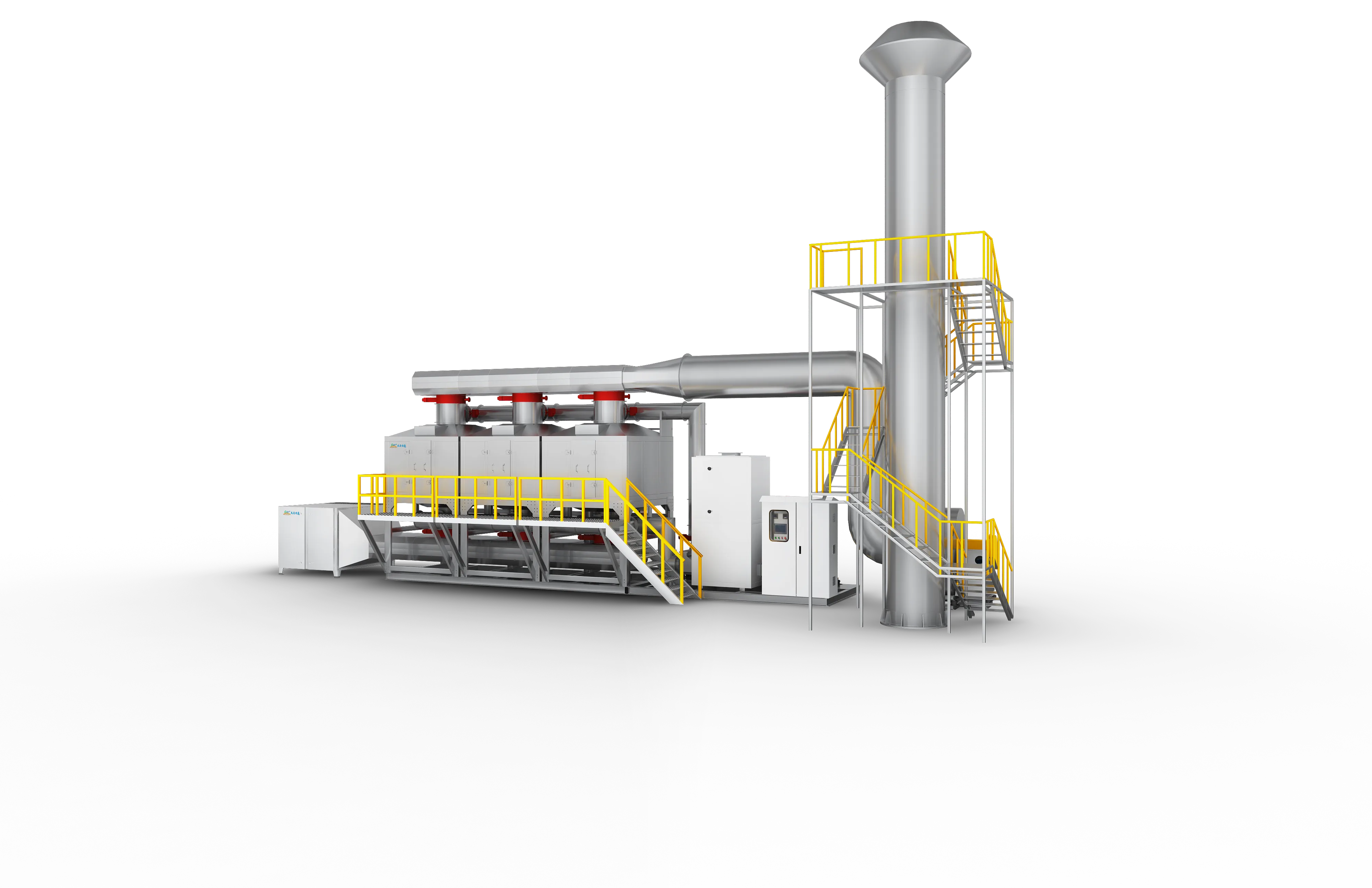
Product images show representative FluxFine configurations. Final dimensions, materials and interfaces follow the approved project design.
Proven Carbon + CO installations
Review documented treatment trains featuring Carbon + CO technology across various industrial processes.
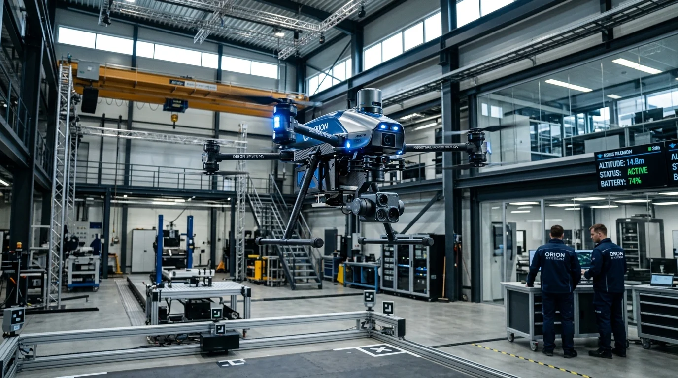
15,000 m³/h (8,830 CFM) · UAV aging, drone spray testing & battery/pesticide soaking
15,000 m³/h VOC & Odor Abatement System for DJI Innovation Drone Testing Facility
PP Wet Chemical Scrubber + G4/F5 Dry Filter + Dual-Stage SUS304 GAC Adsorbers
Read project reference →
700,000 m³/h (412,000 CFM) across 14 trains · Automated lithium-ion polymer battery pack assembly, adhesive dispensing & ultrasonic sealing
700,000 m³/h Multi-Train VOCs & Fluoride Treatment System for NVT Technology Lithium Battery Plants
14-Train PP Alkali Scrubbing (5% NaOH) + Two-Stage Demisting + Cyclic Honeycomb Carbon Adsorption + Catalytic Oxidation (CO, 25:1 Ratio)
Read project reference →120,000 m³/h · Automotive component spray coating
Large-Airflow Automotive Coating VOC Control
Activated carbon concentration + catalytic oxidation
Read project reference →Configure Carbon + CO for your plant
Share measured process data so the engineering team can confirm suitability, pretreatment, equipment size and scope boundaries.
Source basis: Published values are selection references, not a project guarantee.