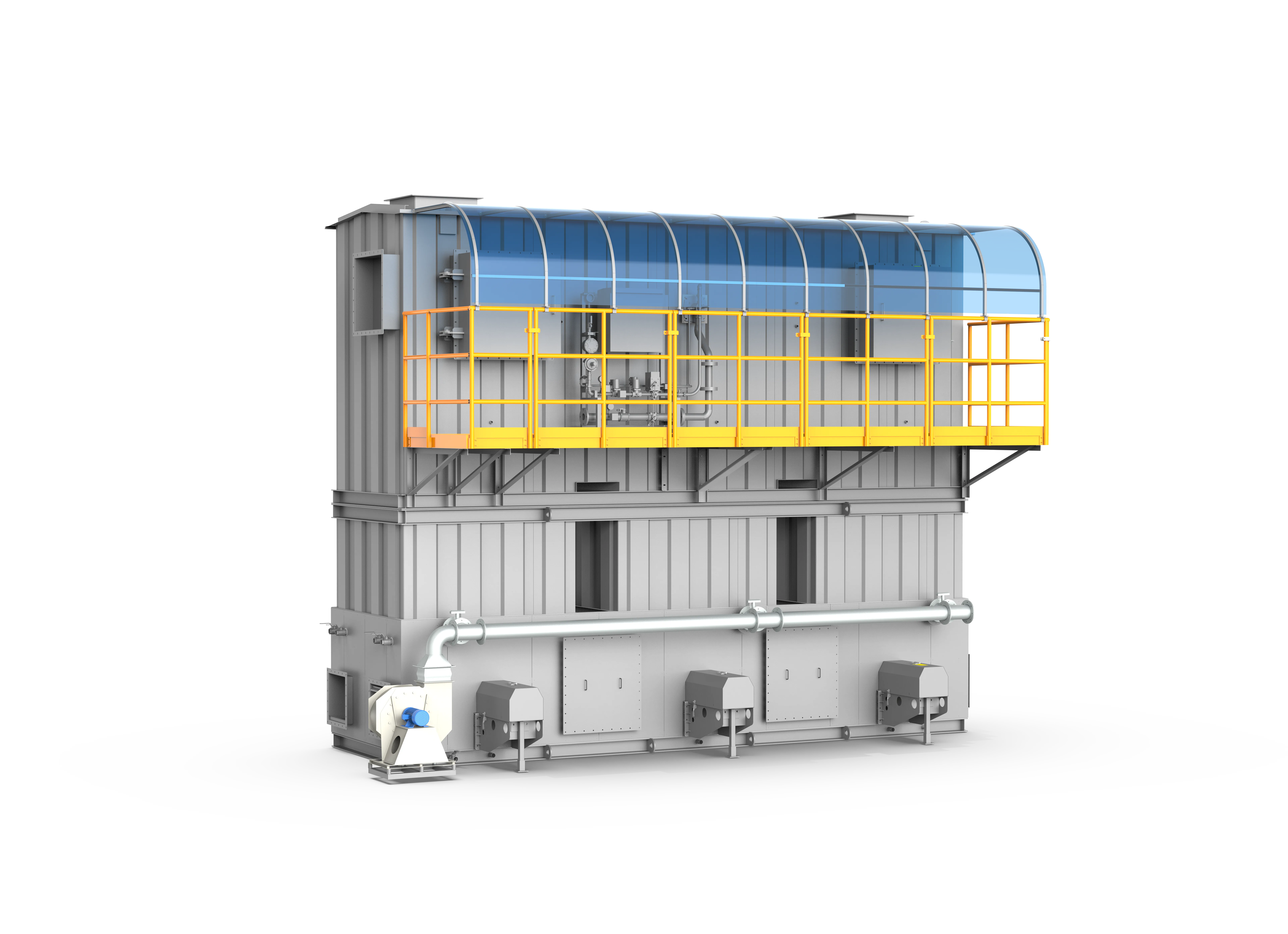
Three-Tower Regenerative Thermal Oxidizer
A premier-grade industrial VOC thermal abatement system that achieves >=99% VOC destruction efficiency and >=95% thermal energy recovery through a classic three-bed alternating heat-exchange and purge process.
Designed around actual process conditions
Engineered for medium-to-high concentration industrial VOC streams, the FluxFine Three-Tower Regenerative Thermal Oxidizer (RTO) represents a highly mature and structurally optimized thermal destruction solution. By integrating an advanced overall modular configuration, the system combines the inlet/outlet headers, switching valves, purge systems, and ceramic beds into a unified, compact structure with a heavy-duty corrugated steel outer casing. This layout minimizes field construction labor and completely eliminates surface corrosion blind spots. Utilizing premium-grade honeycomb or saddle-ring ceramic media, the system guarantees a thermal efficiency of over 95%, enabling self-sustained autoignition at VOC concentrations as low as 1700 mg/m³, delivering superior long-term economy and rigorous emission compliance.
3-Tower RTO / Three-Bed Regenerative Thermal Oxidizer / Multi-Tower Thermal Incinerator / High-Efficiency RTO System
Measured under rated operating conditions with inlet VOC concentrations between 2000 - 6000 mg/m³.
Highly efficient regenerative design minimizes fuel usage and carbon footprint.
Operates completely fuel-free under nominal airflows and VOC heating value of 30,000 kJ/kg.
Operating references and configuration choices
These reference values and modules clarify the scope we evaluate. They are not a substitute for a process-data review or final proposal.
| Engineering reference | Value | How to read it |
|---|---|---|
| Reference airflow | 3,000–50,000 m³/h | Catalog model range; final configuration is project-specific. |
| Reference inlet VOCs | 2,000–6,000 mg/m³ | Condition attached to the catalog purification reference. |
| Thermal recovery | ≥95% | Catalog reference; depends on gas conditions and design. |
| Self-sustaining reference | 1,700 mg/m³ | Calculated under stated source assumptions; not universal. |
Typical modules considered
- Integrated or modular regenerative chambers
- Ceramic media selected for heat recovery and fouling resistance
- Combustion chamber, burner train and high-temperature bypass
- Switching/purge valves with position feedback
- PLC, LEL/temperature monitoring and optional heat-recovery exchanger
Project-specific selection notes
- Confirm whether the actual solvent heat value supports direct oxidation or favors upstream concentration.
- Review halogen, sulfur, silicon, particulate and condensable content before selecting ceramic media and pretreatment.
- Reserve maintenance and crane/platform access for valves, ceramic media and burner components.
Three-bed RTO vs. rotary RTO
Three-bed RTO uses separate regenerative chambers and purge sequencing. Rotary RTO uses a continuous rotary gas-distribution arrangement. Both must be chosen from duty cycle, layout, maintenance strategy, gas chemistry and safety assessment—not from efficiency alone.
- The 2026 catalogue includes coating, printing, pharmaceutical, new-material and PCB applications using three-bed RTO configurations.
- Case airflow/concentration entries are project evidence only and must not be treated as product guarantees.
What we review before specifying Three-Tower RTO
A product name is a starting point, not a final design. These inputs define pretreatment, materials, controls, equipment size and scope boundaries.
Project data to provide
- VOC species, heat value and LEL assessment
- Normal, minimum and peak airflow/concentration
- Inlet temperature, humidity, dust and condensable material
- Operating schedule, available fuel and heat-reuse demand
- Required emission limit, layout and shutdown window
Typical engineered scope
- Process collection and balancing review
- Pretreatment where dust, mist or corrosive components are present
- Regenerative chambers, combustion system and exhaust stack
- PLC, temperature monitoring, gas-concentration and safety interlocks
- Optional hot-air, hot-water or thermal-oil heat recovery
Safety and controls
- Pre-purge, automatic ignition and flame supervision are selected as part of the combustion package.
- LEL monitoring, emergency exhaust/isolation, fire protection and pressure relief are engineered from the gas risk assessment.
- Chamber temperature, fan status, valve/rotor position and permissives should be visible in the control sequence.
- Final alarm and shutdown setpoints are project-specific; they are not universal website specifications.
How it works
The system utilizes three independent regenerative beds (towers) filled with high-temperature resistant ceramic media operating in an alternating, timed sequence: Bed 1 is in inlet/heating mode, Bed 2 is in outlet/cooling mode, and Bed 3 is in purge mode. Raw VOC stream is directed upward through the preheated Bed 1, absorbing heat and approaching the oxidation temperature (750-850°C). It then enters the central combustion chamber where an automated burner system ensures complete oxidation, breaking VOCs down into CO2 and H2O. The ultra-high-temperature clean exhaust passes downward through Bed 2, transferring its heat energy back to the ceramic elements before compliant discharge. Simultaneously, Bed 3 undergoes a fresh air purge to flush out any residual untreated VOCs, preventing the transient emission spikes common in traditional two-tower RTO designs.
- 01Exhaust air collection followed by multi-stage dry filtration to remove heavy particulates, dust, and aerosols.
- 02Raw VOC gas enters Tower 1, flowing upward through preheated ceramic beds and ascending to near-oxidation temperatures.
- 03Complete destructive oxidation in the combustion chamber at 750-850°C, decomposing organics into CO2 and H2O.
- 04High-temperature clean exhaust flows downward through Tower 2, heating the cold ceramic media for the next cycle.
- 05Simultaneous fresh-air or low-concentration clean-gas purge of Tower 3 to eliminate residual VOCs from the prior cycle.
- 06Discharge of cooled, purified exhaust gas through the stack under continuous monitoring.
- 07Pneumatic switching valves index the towers, reversing the roles of Tower 1, 2, and 3 to maintain continuous operation.
- Medium-to-high concentration organic exhaust streams (2000 - 6000 mg/m³) with moderate-to-large airflows.
- Complex, multi-component VOC mixtures containing solvents like benzene, toluene, xylene, esters, ketones, alcohols, and ethers.
- Manufacturing plants requiring continuous (24/7) or highly stable cyclical operations, such as chemical synthesis, paint lines, printing, packaging, and lithium battery manufacturing.
- Industrial environments demanding ultra-low emissions and minimal auxiliary fuel consumption (reaches self-sustaining auto-thermal state at 1700 mg/m³).
- Strict Concentration Limits: Inlet VOC concentrations must be kept below safety thresholds, generally capped below 25% LEL (Lower Explosive Limit); automatic emergency bypass must open if limits are exceeded.
- Particulate Control: Inlet dust and sticky particulates must be pre-treated to prevent fouling and clogging of the regenerative ceramic media channels.
- Halogen and Sulfur Restrictions: High-sulfur or high-chlorine streams should be avoided or treated with wet scrubbers to prevent acid-gas corrosion of the steel casing and RTO internal linings.
- Condensation Prevention: For high-humidity or cold-environment installations, proper piping insulation must be implemented to prevent solvent condensation and pipe blockages.
- Pneumatic Valve Maintenance: The high-frequency pneumatic switching valves must undergo regular seal inspections to prevent gas bypass and channeling (leakage rate must be kept <= 0.05%).
Typical pollutants
- Benzene
- Toluene
- Xylene
- Ethyl Acetate
- Butyl Acetate
- MEK (Methyl Ethyl Ketone)
- MIBK
- Isopropanol
- Ethanol
- Styrene
- Cyclohexanone
- NMP
- DMSO
- Phenol
Engineering features
- Integrated Modular Structure: Combines gas inlets, outlets, switching valves, and ceramic chambers into a pre-engineered, unified layout to slash on-site piping installation times.
- High-Performance Ceramic Media: Equipped with customized high-capacity honeycomb or saddle-ring ceramic elements withstanding up to 1200°C with exceptional thermal storage properties.
- Valveless Leak-Free Performance: Premium pneumatic switching valves featuring a dual 'soft seal + air seal' design, ensuring a leakage rate of <= 0.05% and a lifespan exceeding 1 million cycles.
- Heavy-Duty Corrugated Outer Casing: Outer shell utilizing structural corrugated plates to eliminate external stiffeners, eliminating paint blind spots and delivering exceptional corrosion protection.
- Double-Insulated Thermal Safeguards: Internal insulation utilizing RTO-specialized aluminum-silicate ceramic fiber modules (rated for 1260°C) with a thickness of >= 250-300mm, maintaining outer surface temperatures below 60°C.
- 3-Tier Cascade Thermal Safety: Automated logic including 850°C bypass regulation, 900°C fresh air dilution, and 950°C emergency system shutoff.
- Global Compliance & Safety Standards: Engineered in accordance with NFPA 86 (US) oven/furnace safety standards and CE ATEX directives for industrial thermal protection.
Available options
- Honeycomb Ceramic Regenerative Media (Optimal for high thermal storage and low pressure drop)
- Saddle-Ring Ceramic Regenerative Media (Optimal for superior clog resistance and heavy solvent loads)
- Waste Heat Recovery Skid (Hot-air bypass to recycle combustion thermal energy back to ovens, ovens, or space heating)
- UPS Backup Control Power (Enables safe shutdown sequence, opening emergency bypasses and purging the combustion chamber during power outages)
- LEL Online Monitoring & Fast-Response Bypass Valve System
Relevant industries
Printing & Laminating
Gravure, flexible packaging, lamination, optical film and continuous web processes.
Coating & Surface Finishing
Industrial paint, UV coating, adhesive, metal finishing and multi-booth surface processes.
Automotive & E-Mobility
OEM parts, e-bike, and industrial spray booth exhaust.
Chemical Industry
Resins, coatings, waterproofing, and specialty chemicals.
Pharmaceutical & Medical
Solvent exhaust from synthesis, coating, and finishing.
New Materials & New Energy
Battery materials, functional films, composites and advanced material production.
Heavy Machinery & Shipbuilding
Large booth coating and high-airflow paint shops.
General technology selection
These answers explain the selection path. Final performance, safety scope and dimensions follow the approved project design.
When is a direct RTO preferable to a concentrator system?
A direct RTO is often evaluated when the inlet VOC load and heat value support efficient thermal oxidation. Large, dilute streams may instead benefit from upstream concentration. The final answer depends on the full airflow and concentration profile.
Can an RTO accept paint mist or dust?
Not without suitable pretreatment. Mist, particulate, sticky material and corrosive components can foul regenerative media or create safety and maintenance risks.
Source basis: 2026 product catalogue and VOCs equipment source. Thermal efficiency and removal figures are project-specific reference values.
Specific product Q&A
Why is a three-bed RTO better than a two-bed RTO for VOC destruction efficiency?
A two-bed RTO experiences a brief pulse of unburned VOCs (a 'puff') every time the flow-direction valves switch, which can cause the system to fail strict emission limits (capping efficiency around 98%). A three-bed RTO introduces a third 'purge' chamber. Before a chamber transitions from exhaust back to inlet, it is purged with clean air, sweeping any residual unburned VOCs back into the combustion chamber. This eliminates the puff effect and allows a three-bed RTO to consistently achieve >=99% Destruction Removal Efficiency (DRE).
What is the auto-thermal concentration threshold for a 3-bed RTO?
With standard high-density structured ceramic media, a three-bed RTO can typically achieve 95% thermal energy recovery (TER). At this thermal efficiency, the auto-thermal threshold—the point where the VOC concentration contains enough calorific value to sustain the 800°C combustion temperature without supplemental burner fuel—is approximately 1.5 to 2.0 g/m³ (depending on the specific solvent's heat of combustion). Operating above this threshold means the RTO runs fuel-free.
How to prevent VOC pressure spikes during RTO valve switching?
Rapid valve switching in an RTO can cause abrupt backpressure spikes, leading to fugitive emissions upstream in the production facility. FluxFine mitigates this by using precision-machined poppet valves driven by proportional pneumatics or servo motors, coupled with overlapping valve timing logic in the PLC. This ensures the exhaust path is never completely closed during a cycle transition, maintaining stable static pressure across the upstream process network.
Equipment views
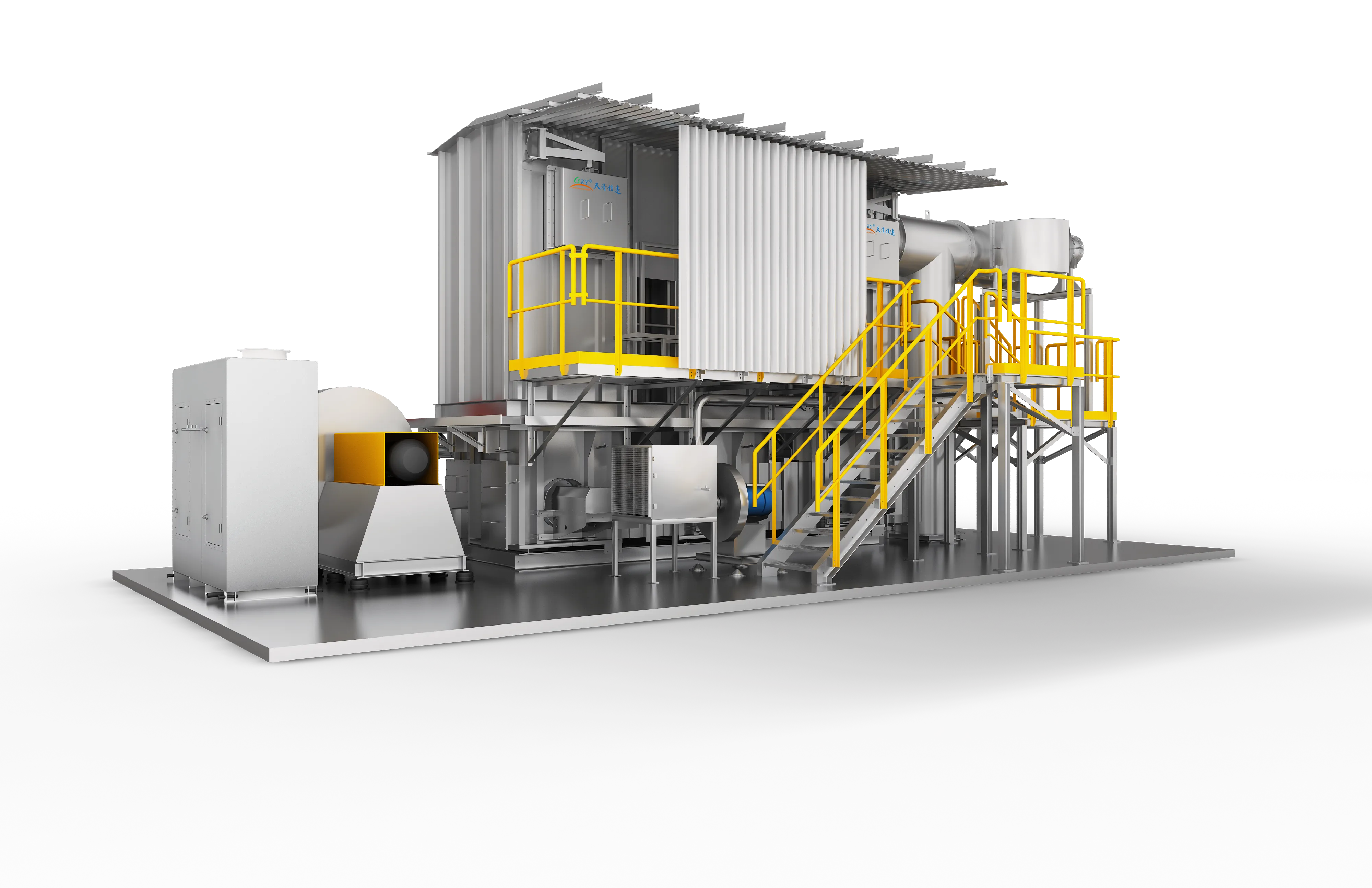
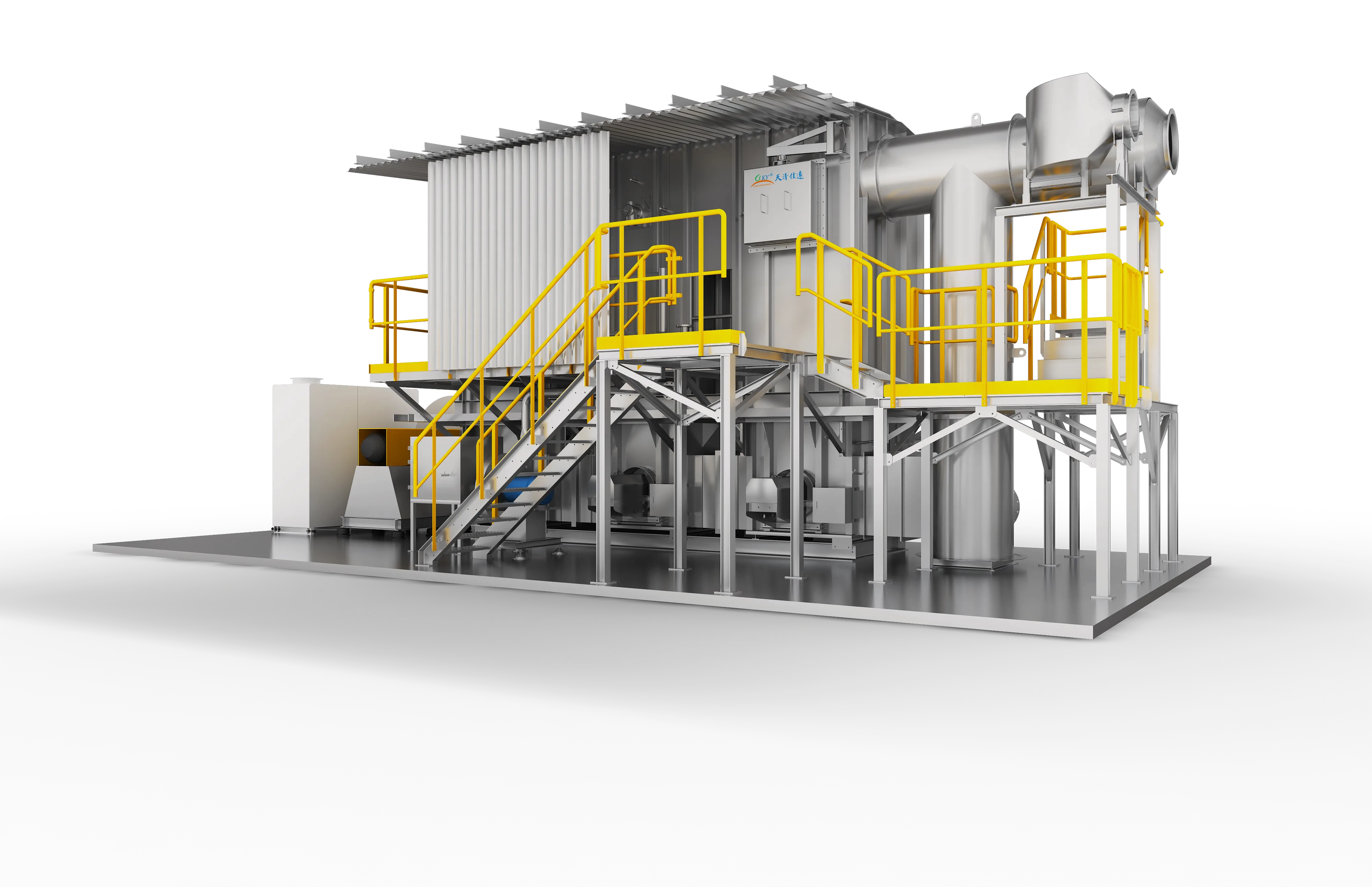
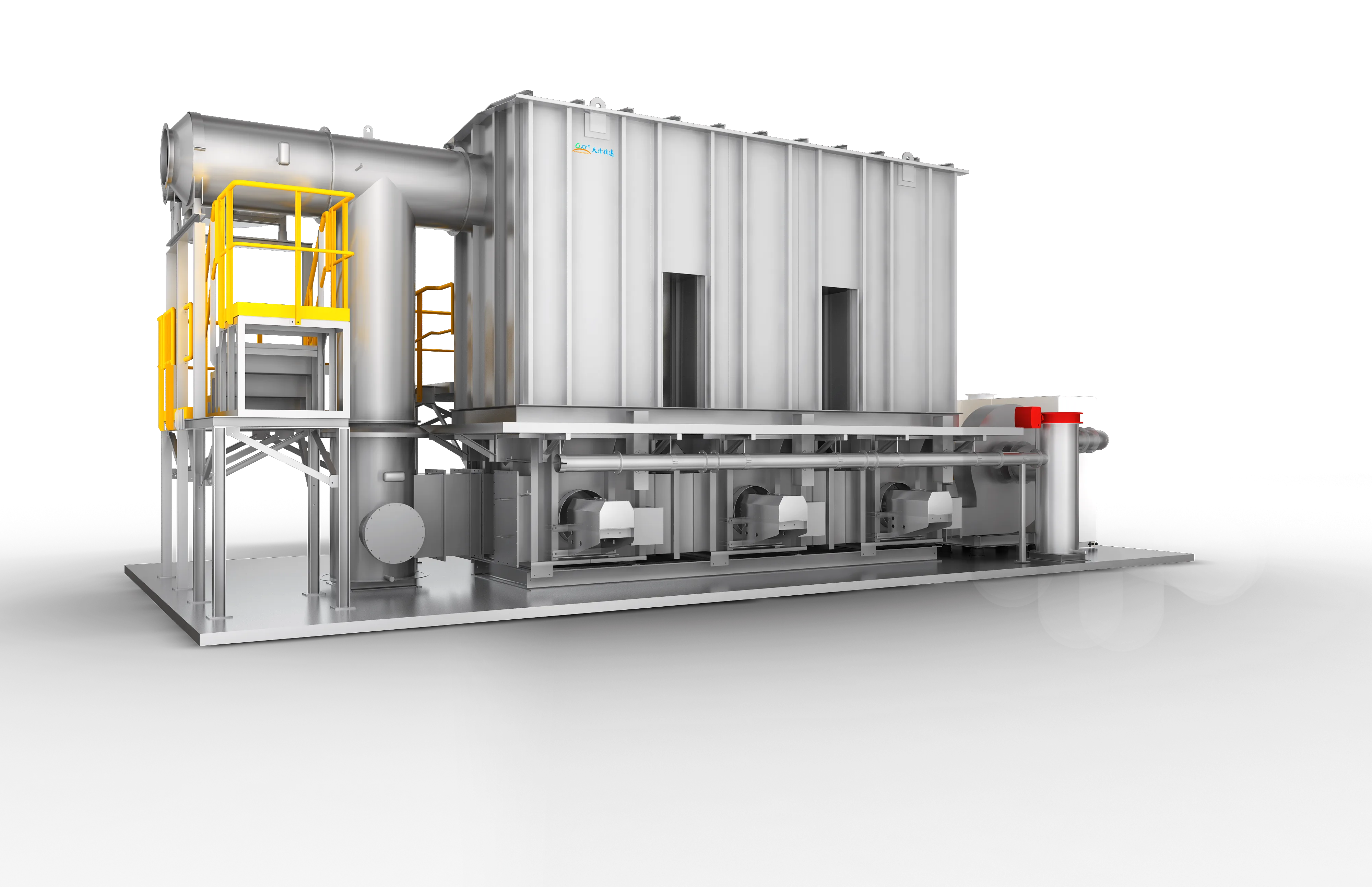
Product images show representative FluxFine configurations. Final dimensions, materials and interfaces follow the approved project design.
Technical Parameters
Detailed parameter models for engineering selection and sizing. Note that dimensions and efficiencies are for reference under nominal conditions.
| Model | Airflow (m³/h) | Inlet VOCs (mg/m³) | Efficiency | Heat Recovery | Burner Power | Dimensions (m) |
|---|---|---|---|---|---|---|
| TQJY-RTO-G3 | 3000 | 1700 | ≥99% | ≥95% | 150,000 kcal/h (174 kW / 0.6 MMBtu/hr) | 5.6×1.6×4.6 |
| TQJY-RTO-G5 | 5000 | 1700 | ≥99% | ≥95% | 250,000 kcal/h (290 kW / 1.0 MMBtu/hr) | 5.6×1.9×5.2 |
| TQJY-RTO-G8 | 8000 | 1700 | ≥99% | ≥95% | 370,000 kcal/h (430 kW / 1.5 MMBtu/hr) | 6.5×2.2×5.3 |
| TQJY-RTO-G10 | 10000 | 1700 | ≥99% | ≥95% | 500,000 kcal/h (581 kW / 2.0 MMBtu/hr) | 7.4×2.2×5.4 |
| TQJY-RTO-G15 | 15000 | 1700 | ≥99% | ≥95% | 750,000 kcal/h (872 kW / 3.0 MMBtu/hr) | 8.3×2.5×5.5 |
| TQJY-RTO-G20 | 20000 | 1700 | ≥99% | ≥95% | 750,000 kcal/h (872 kW / 3.0 MMBtu/hr) | 9.2×2.8×5.7 |
| TQJY-RTO-G25 | 25000 | 1700 | ≥99% | ≥95% | 1,000,000 kcal/h (1,163 kW / 4.0 MMBtu/hr) | 10.1×3.1×5.7 |
| TQJY-RTO-G30 | 30000 | 1700 | ≥99% | ≥95% | 1,250,000 kcal/h (1,453 kW / 5.0 MMBtu/hr) | 10.1×3.4×6.0 |
| TQJY-RTO-G35 | 35000 | 1700 | ≥99% | ≥95% | 1,250,000 kcal/h (1,453 kW / 5.0 MMBtu/hr) | 11.0×3.4×6.2 |
| TQJY-RTO-G40 | 40000 | 1700 | ≥99% | ≥95% | 1,500,000 kcal/h (1,744 kW / 6.0 MMBtu/hr) | 12.8×3.4×6.2 |
| TQJY-RTO-G45 | 45000 | 1700 | ≥99% | ≥95% | 1,500,000 kcal/h (1,744 kW / 6.0 MMBtu/hr) | 13.7×3.4×6.3 |
| TQJY-RTO-G50 | 50000 | 1700 | ≥99% | ≥95% | 1,850,000 kcal/h (2,151 kW / 7.3 MMBtu/hr) | 14.6×3.4×6.5 |
Proven Three-Tower RTO installations
Review documented treatment trains featuring Three-Tower RTO technology across various industrial processes.
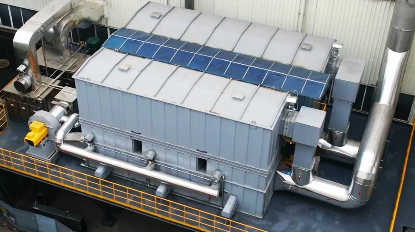
60,000 m³/h (35,300 CFM) · AC heat exchanger coil thermal degreasing ovens (stamping & drawing lubricant VOCs)
60,000 m³/h Dual 3-Bed RTO Thermal Abatement System for Haier Smart Home (Chongqing)
Dual-Train 3-Bed RTO (35k + 25k m³/h) + Stainless Wire Mesh Demisters + 25m Combined Stack
Read project reference →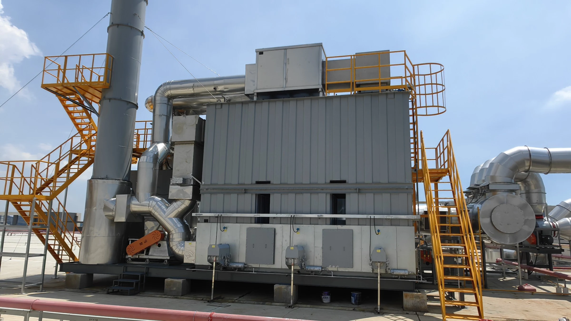
450,000 m³/h (265,000 CFM) · Architectural aluminum profile automated fluorocarbon (PVDF) spray coating and curing lines
450,000 m³/h Dual Zeolite Rotor & 3-Bed RTO System for JMA Aluminum Fluorocarbon Coating Lines
Dual-Train Zeolite Rotor (2×220k m³/h) + 3-Bed RTO (55k m³/h) + Dual Jet Scrubbers + 4-Stage Dry Filtration
Read project reference →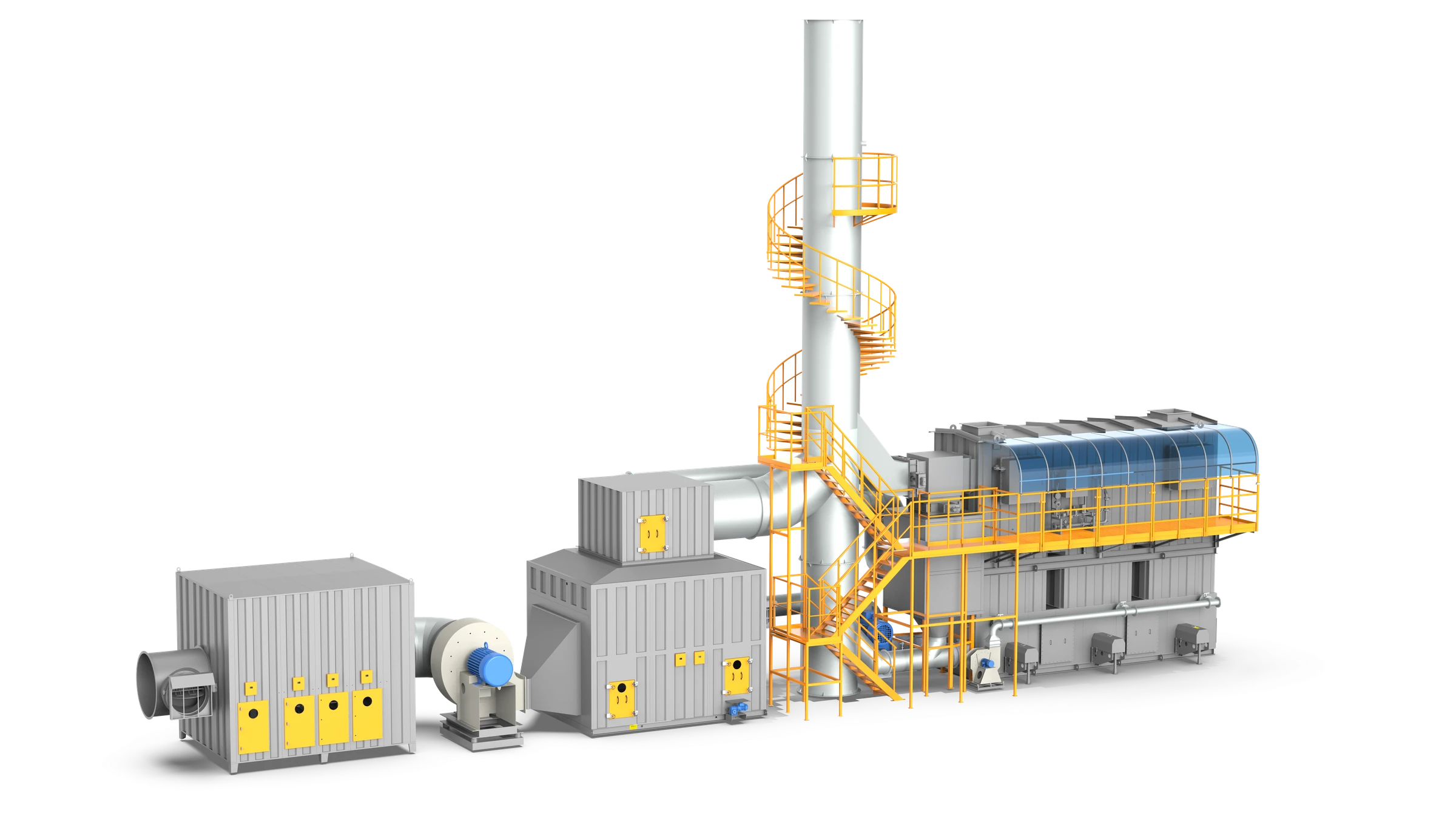
200,000 m³/h (117,600 CFM) · Commercial vehicle & tanker spray coating and curing
200,000 m³/h Zeolite Drum & 3-Bed RTO System for CIMC Vehicles
5-Stage HEPA Dry Filtration (G4-H11) + Cylindrical Zeolite Drum Concentrator + 3-Bed RTO
Read project reference →Configure Three-Tower RTO for your plant
Share measured process data so the engineering team can confirm suitability, pretreatment, equipment size and scope boundaries.
Source basis: Published values are selection references, not a project guarantee.