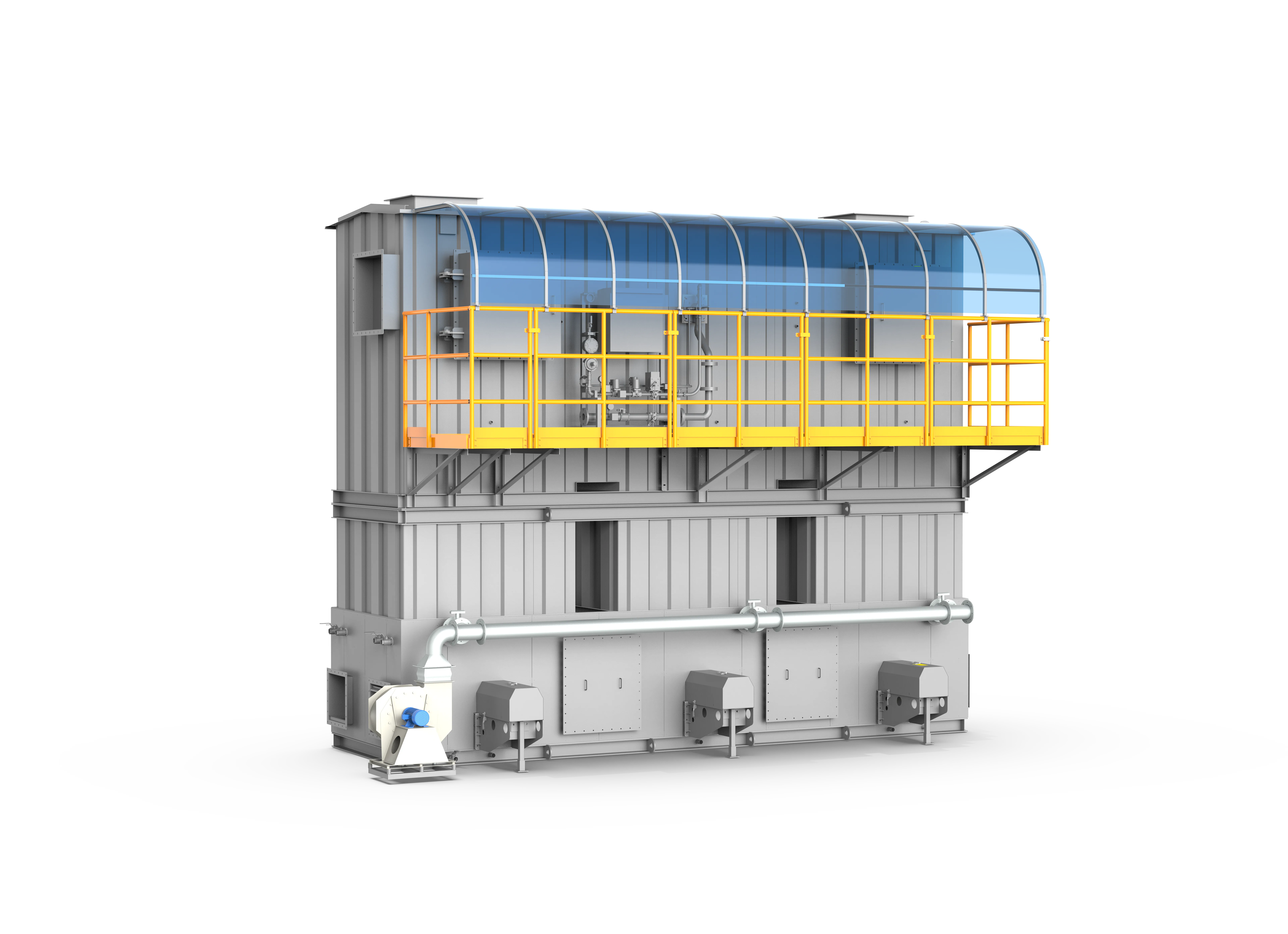
RTO Thermal Oxidizer
Regenerative thermal oxidizers for medium-to-high VOCs loads with high thermal efficiency and stable long-term operation.
Where RTO fits
FluxFine RTO systems oxidize organic exhaust in a high-temperature chamber while recovering heat through ceramic media beds. They are built for continuous industrial duty where solvent mixes change and long-term compliance cannot depend on fragile catalyst beds alone.
Medium–high concentration VOCs, complex solvent mixes, heat recovery duty
Catalog reference; project-specific
Typical RTO design target
Medium-to-high VOC load
How the system works
Process gas cycles through regenerative chambers: one bed preheats inlet air, the combustion chamber destroys VOCs, and another bed recovers heat before stack discharge. Valve sequencing (poppet or rotary) keeps thermal efficiency high and outlet temperatures controlled.
- 01Pre-filter and condition the process exhaust as required.
- 02Ceramic media preheats the incoming gas using recovered energy.
- 03The oxidation chamber converts VOCs to carbon dioxide and water.
- 04A second media bed recovers heat before compliant stack discharge.
Choose by process conditions
| Configuration | Description | Best fit | Source metric |
|---|---|---|---|
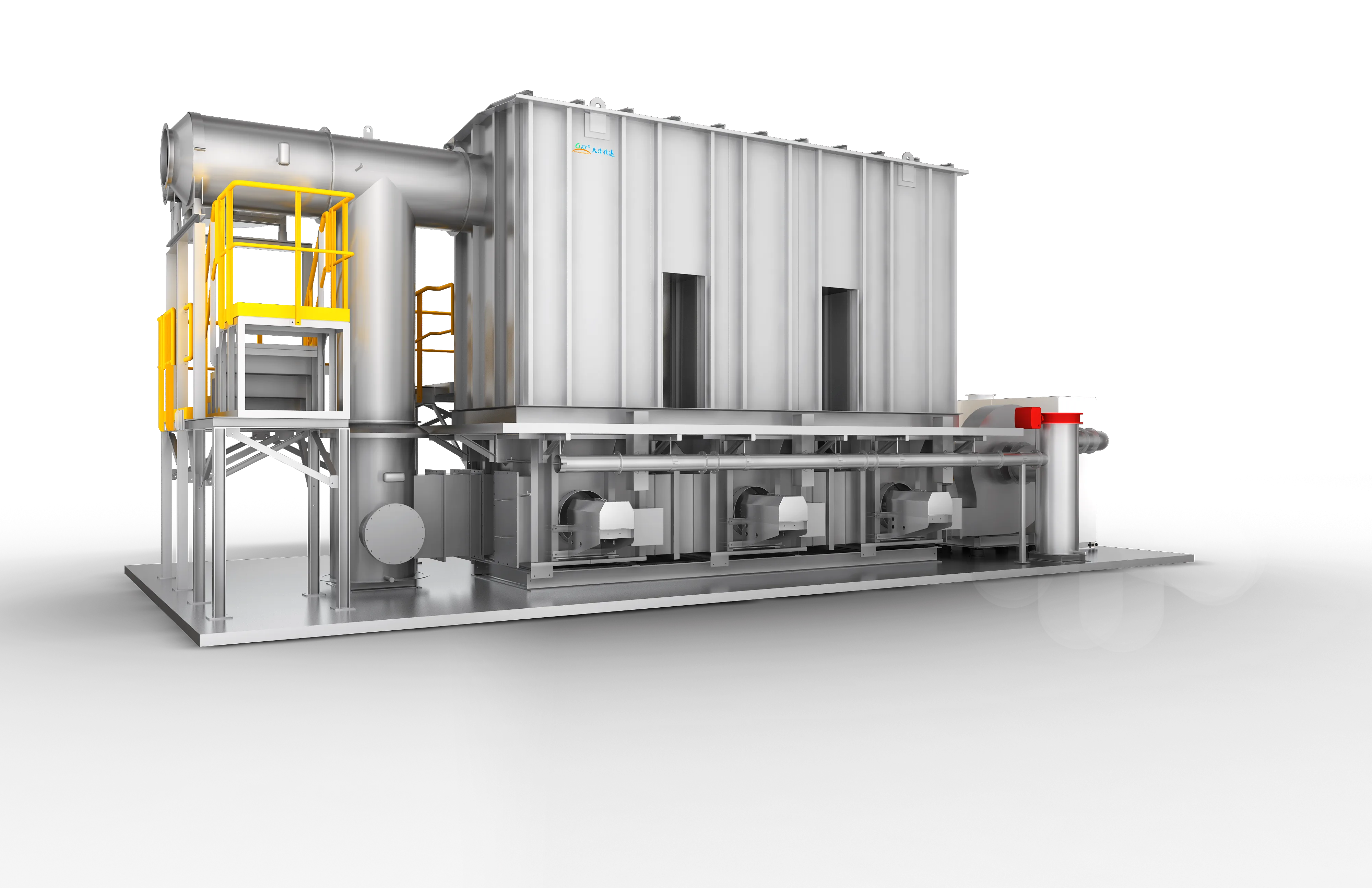
| Three-Bed RTO | Three regenerative chambers with sequenced valves for stable continuous treatment and low purge loss. | Large continuous lines, complex solvent mixtures, and stringent removal duty. | Catalog reference: >=98% purification, >=95% heat recovery |
| Rotary RTO | A compact circular regenerator with rotary gas distribution instead of multiple poppet valves. | Sites that need a compact footprint and broad airflow flexibility. | Project-specific |
| Zeolite Rotor + RTO | Concentrates large-volume dilute exhaust before thermal oxidation to reduce oxidizer size and fuel demand. | Coating, printing, electronics, and other high-airflow low-concentration processes. | Catalog reference: >=98% combined-system purification |
Typical pollutants
- Alkanes and olefins
- Alcohols and ketones
- Ethers and esters
- Aromatics and mixed solvents
Engineering features
- Combustion, equipment, and ductwork safety interlocks
- Poppet-valve or rotary distribution options
- PLC monitoring, alarms, and fault diagnostics
- Secondary hot-air, hot-water, or heat-transfer-oil recovery options
- Integrated control with coating, printing, and drying lines
Selection cautions
- Final sizing depends on solvent chemistry, LEL margin, temperature, and concentration variability.
- Chlorinated, sulfur-bearing, silicon-bearing, or highly corrosive streams require dedicated review and pretreatment.
What determines the final treatment train
Technology selection begins with process data. The same technology can require different pretreatment, materials, controls and maintenance provisions from one plant to another.
Information to confirm
- VOC species, heat value and LEL assessment
- Normal, minimum and peak airflow/concentration
- Inlet temperature, humidity, dust and condensable material
- Operating schedule, available fuel and heat-reuse demand
- Required emission limit, layout and shutdown window
Typical system scope
- Process collection and balancing review
- Pretreatment where dust, mist or corrosive components are present
- Regenerative chambers, combustion system and exhaust stack
- PLC, temperature monitoring, gas-concentration and safety interlocks
- Optional hot-air, hot-water or thermal-oil heat recovery
Selection boundaries
- Pre-purge, automatic ignition and flame supervision are selected as part of the combustion package.
- LEL monitoring, emergency exhaust/isolation, fire protection and pressure relief are engineered from the gas risk assessment.
- Chamber temperature, fan status, valve/rotor position and permissives should be visible in the control sequence.
- Final alarm and shutdown setpoints are project-specific; they are not universal website specifications.
Source basis: 2026 product catalogue and VOCs equipment source. Thermal efficiency and removal figures are project-specific reference values.
Products using this technology
Three-Tower RTO
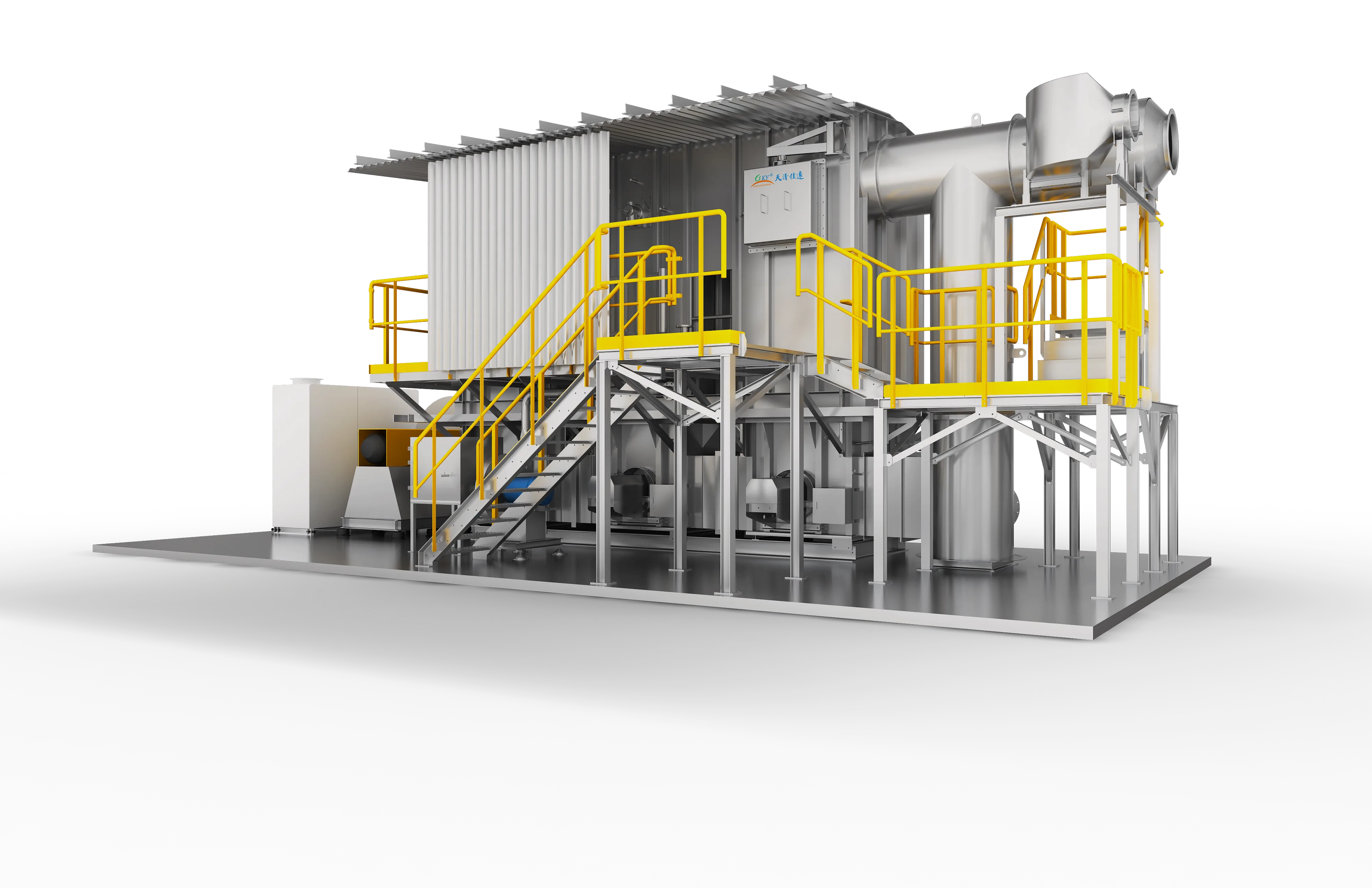
A premier-grade industrial VOC thermal abatement system that achieves >=99% VOC destruction efficiency and >=95% thermal energy recovery through a classic three-bed alternating heat-exchange and purge process.
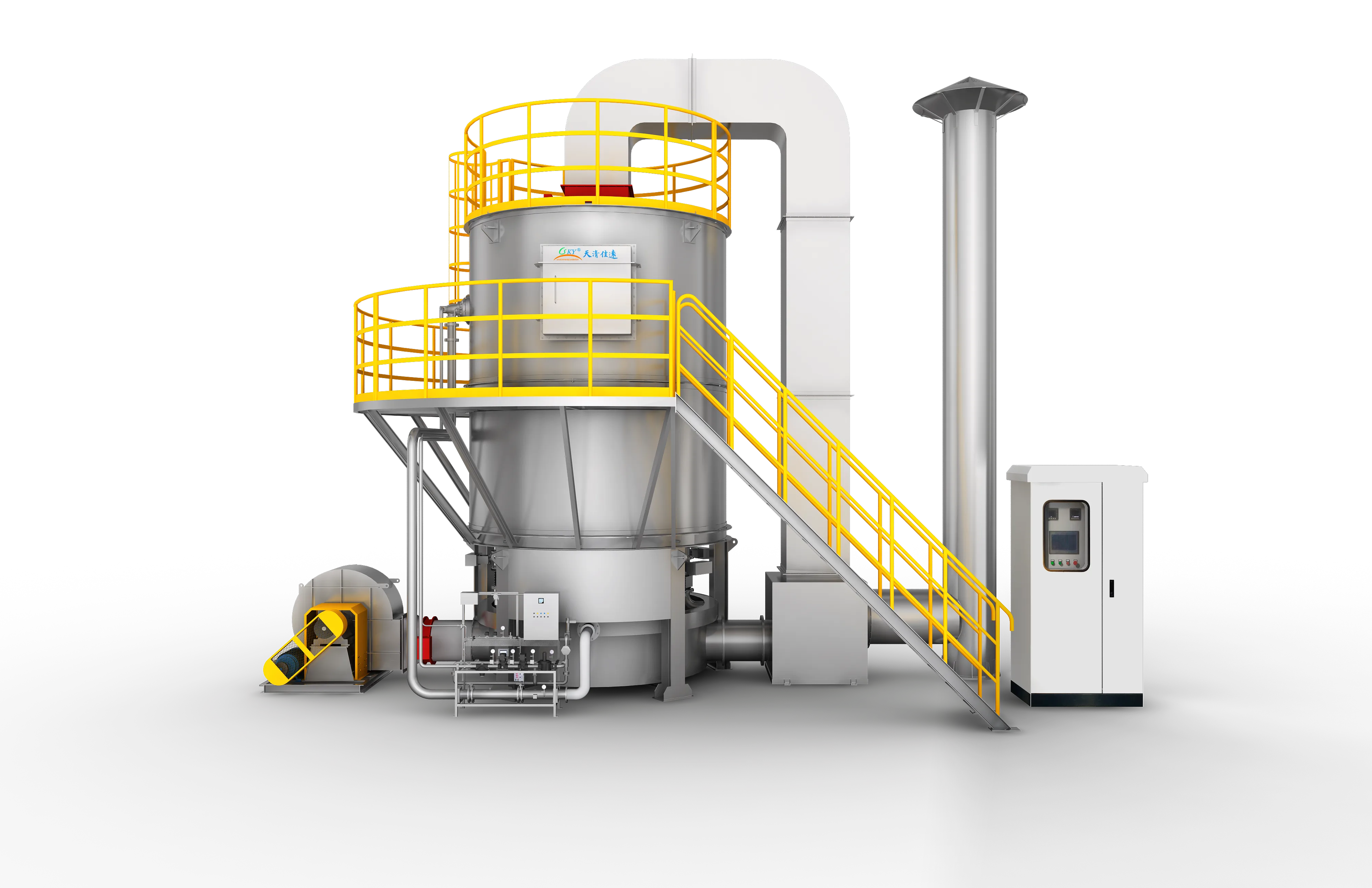
Rotary RTO
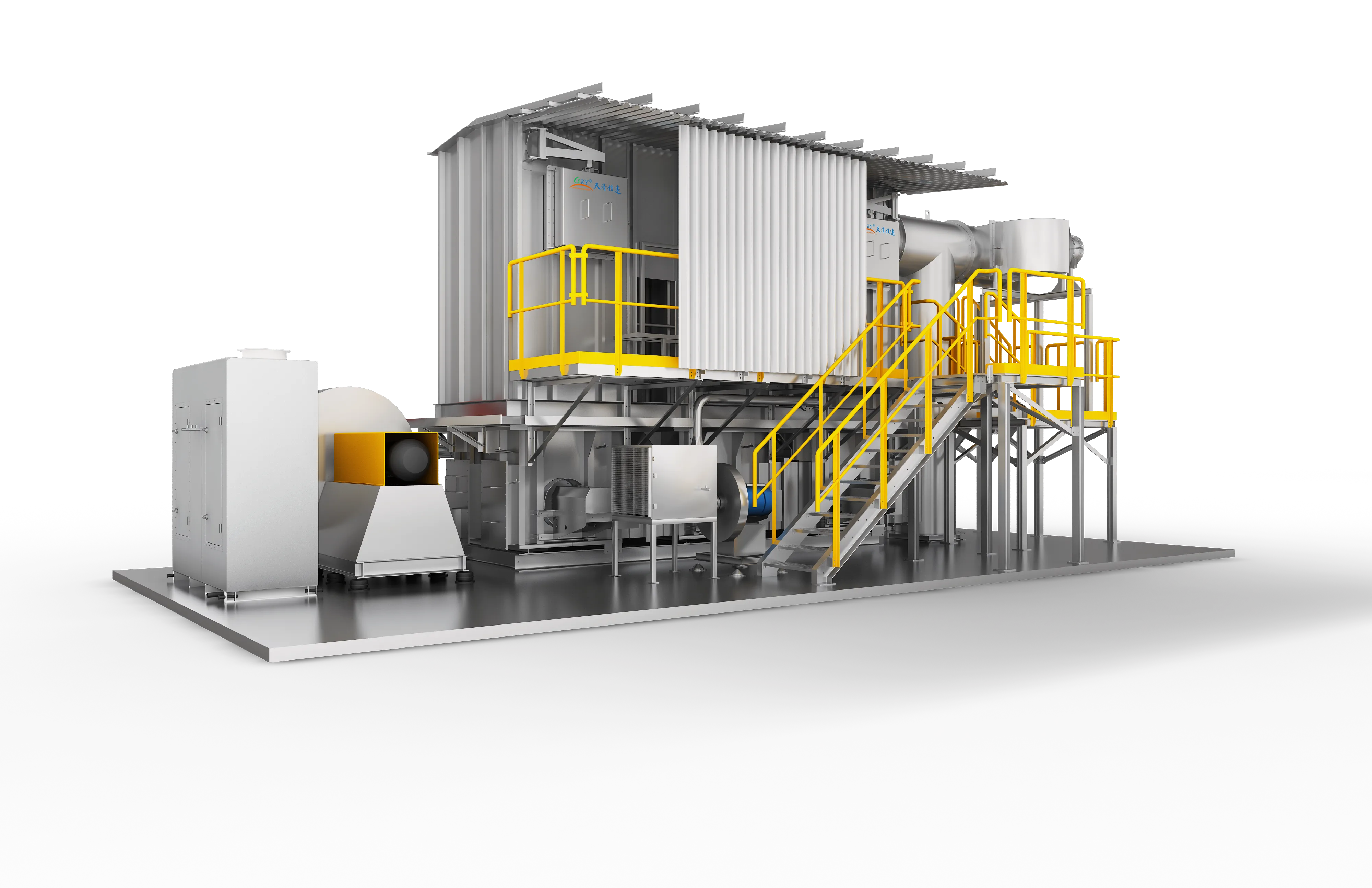
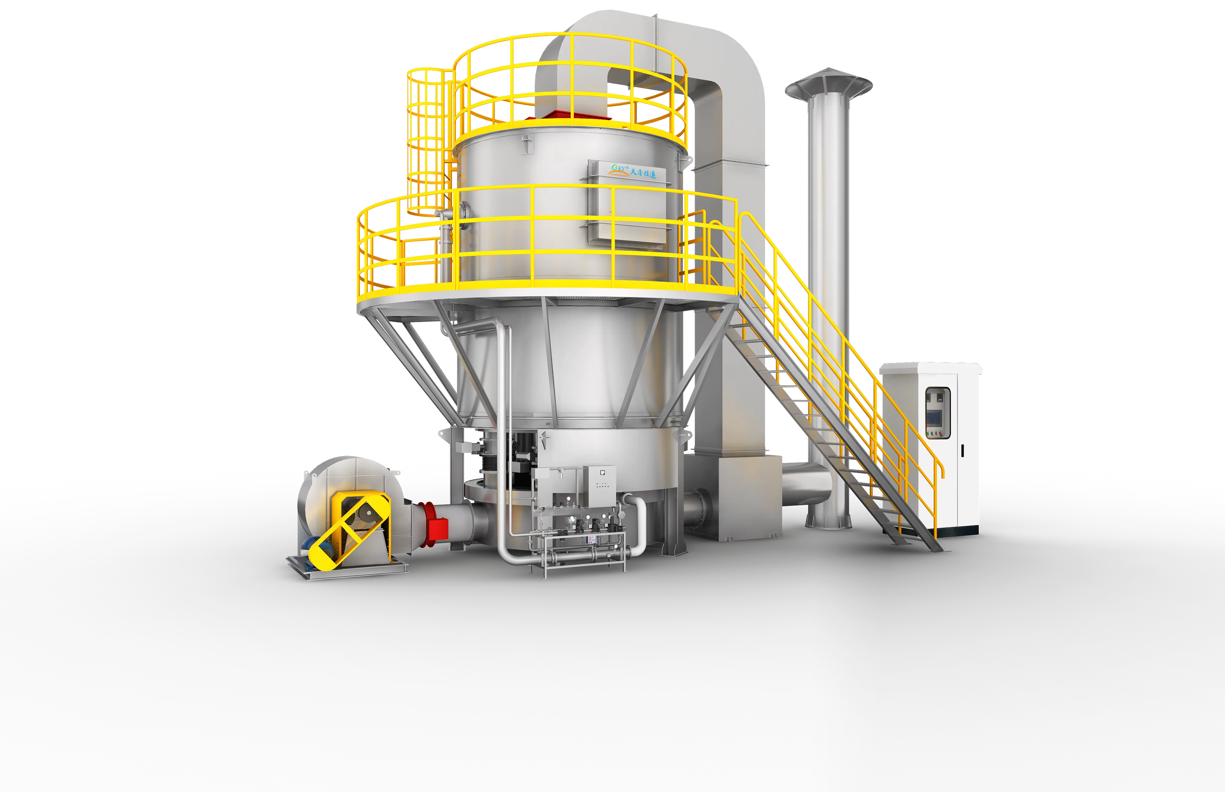
A next-generation RTO system utilizing a continuously rotating gas distributor instead of switching valves, providing stable thermal destruction of VOCs with >= 99% purification efficiency, >= 95% thermal recovery, and zero pressure spikes.
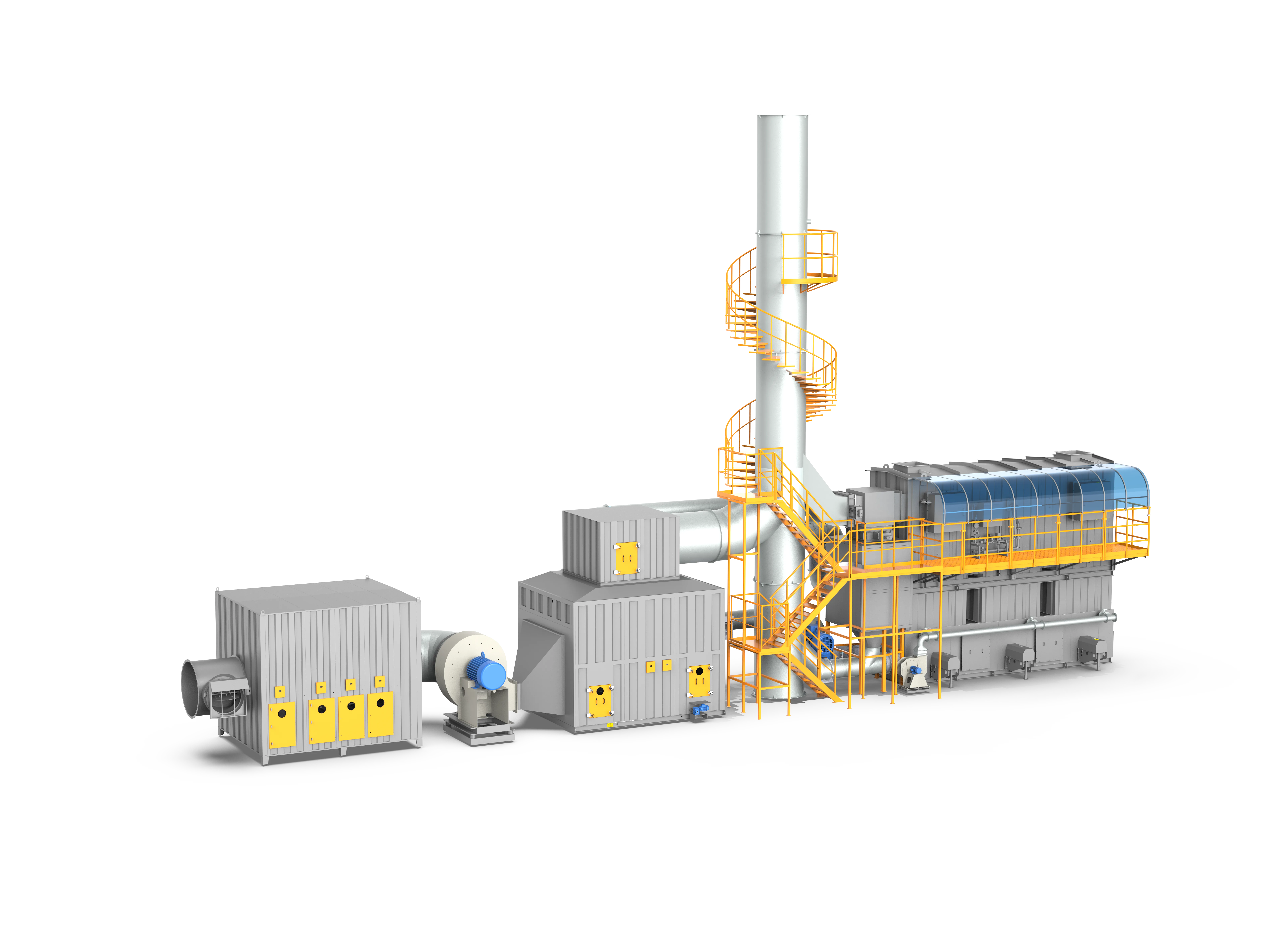
Rotor + 3-Tower RTO
The premier system for large-airflow, low-concentration VOC emissions, combining a hydrophobic zeolite rotor for 10-40x gas enrichment with a mature three-tower RTO for complete destructive oxidation, cutting energy costs by 40%-60%.
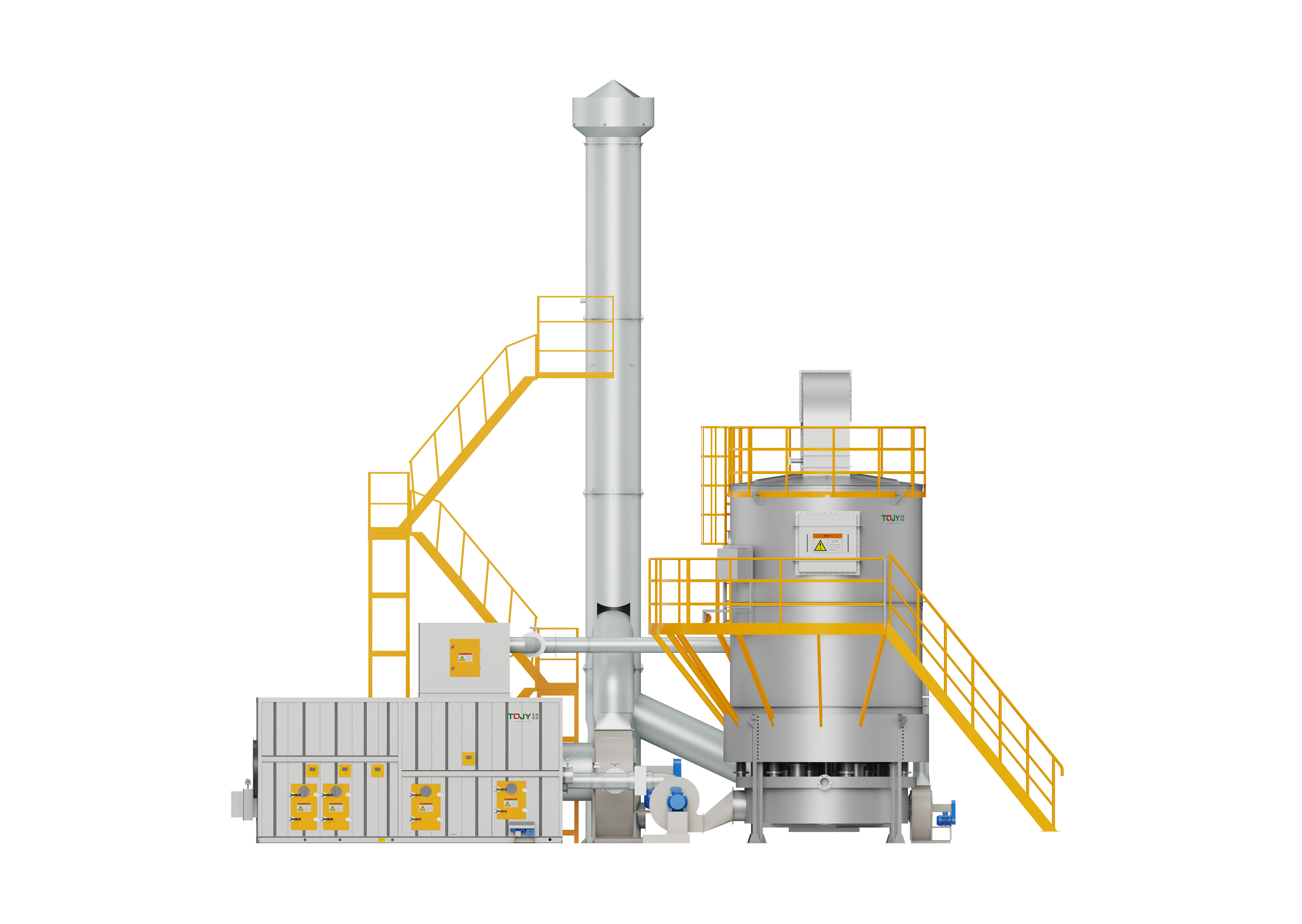
Rotor + Rotary RTO
The ultimate high-end VOC abatement configuration, marrying a hydrophobic zeolite rotor for 10-40x gas concentration with a valveless Rotary RTO for continuous, pulse-free, and highly energy-efficient thermal destruction (efficiency >= 99.8%).
Selection questions
When is a direct RTO preferable to a concentrator system?
A direct RTO is often evaluated when the inlet VOC load and heat value support efficient thermal oxidation. Large, dilute streams may instead benefit from upstream concentration. The final answer depends on the full airflow and concentration profile.
Can an RTO accept paint mist or dust?
Not without suitable pretreatment. Mist, particulate, sticky material and corrosive components can foul regenerative media or create safety and maintenance risks.
Equipment views
Specify RTO for your plant
Performance depends on actual gas composition, inlet load, temperature and operating schedule. Share process data for a configuration review.