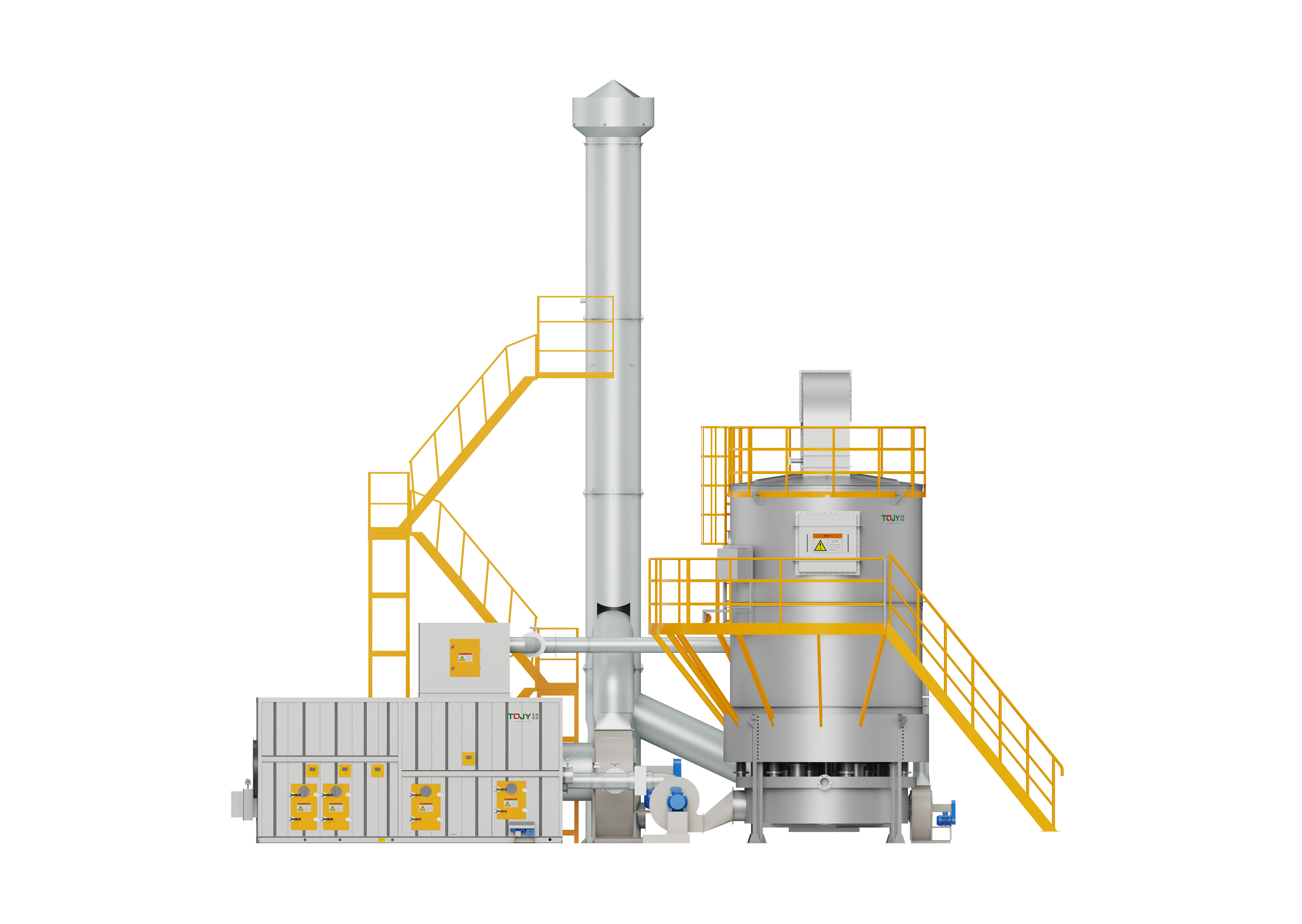
Zeolite Rotor + Rotary RTO Integrated System
The ultimate high-end VOC abatement configuration, marrying a hydrophobic zeolite rotor for 10-40x gas concentration with a valveless Rotary RTO for continuous, pulse-free, and highly energy-efficient thermal destruction (efficiency >= 99.8%).
Designed around actual process conditions
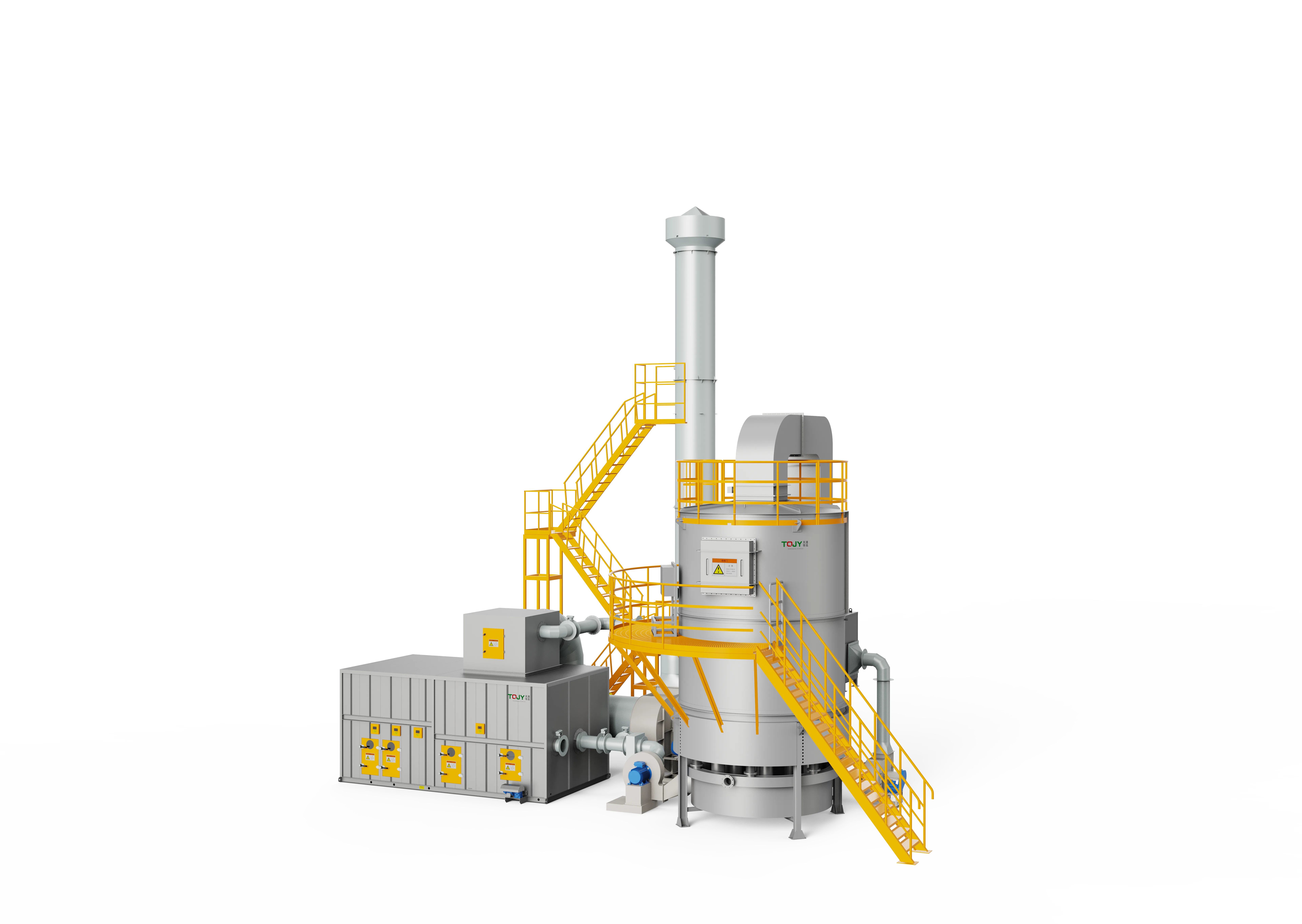
For industrial plants running large-airflow, low-concentration operations under strict environmental standards, the FluxFine Zeolite Rotor + Rotary RTO represents the peak of emission control engineering. This elite system integrates advanced zeolite concentration with a valveless, rotating-distributor RTO. By replacing fast-acting poppet valves with a continuously rotating gas distributor, the system completely eliminates pipeline pressure pulses and valve wear. The combined unit occupies a minimal footprint, operates in near-silence, and delivers outstanding VOC removal efficiency (>= 99.8%) with optimized lifecycle economics.
Concentrator with Rotary RTO / Valveless Rotor-RTO Package / High-End Concentrator-Oxidizer System
Provides maximum regulatory compliance for highly regulated industrial zones.
Rotor concentration and valveless heat recovery significantly cut active gas burn.
Eliminates the risk of exhaust hood backflow on high-precision printing or coating heads.
Operating references and configuration choices
These reference values and modules clarify the scope we evaluate. They are not a substitute for a process-data review or final proposal.
| Engineering reference | Value | How to read it |
|---|---|---|
| Best-fit pattern | High airflow / dilute compatible VOCs | Selection depends on solvent chemistry, pretreatment and the project heat balance. |
| Treatment route | Zeolite concentration → rotary RTO | The rotor and oxidizer must be designed as one linked operating system. |
| Layout basis | Integrated or split | Final arrangement follows site footprint, duct routing and maintenance access. |
Typical modules considered
- Source capture, filtration and pretreatment selected to protect the rotor
- Zeolite rotor with desorption, cooling, sealing and differential-pressure controls
- Rotary regenerative oxidizer with combustion and distribution controls
- Linked heat-recovery, PLC, temperature/pressure and safety-interlock package
Project-specific selection notes
- Evaluate paint mist, oil, dust, high-boiling compounds and corrosive components before confirming rotor compatibility.
- Model the desorption load, rotary-RTO heat balance and normal/peak production modes together.
- Plan seal, drive, ceramic and filter maintenance access before locking the equipment footprint.
Rotary RTO or three-bed RTO downstream?
Both configurations can be paired with zeolite concentration. Rotary RTO is often evaluated where a compact continuous gas-distribution arrangement suits the site; three-bed RTO may suit a different maintenance, valve and layout preference. The final decision follows the actual duty and safety review.
- The supplied product sources describe zeolite concentration paired with rotary RTO as a combined VOC treatment configuration.
- No generic airflow, removal or energy-saving promise is applied: those values require a confirmed process-data and heat-balance review.
What we review before specifying Rotor + Rotary RTO
A product name is a starting point, not a final design. These inputs define pretreatment, materials, controls, equipment size and scope boundaries.
Project data to provide
- VOC species, heat value and LEL assessment
- Normal, minimum and peak airflow/concentration
- Inlet temperature, humidity, dust and condensable material
- Operating schedule, available fuel and heat-reuse demand
- Required emission limit, layout and shutdown window
Typical engineered scope
- Process collection and balancing review
- Pretreatment where dust, mist or corrosive components are present
- Regenerative chambers, combustion system and exhaust stack
- PLC, temperature monitoring, gas-concentration and safety interlocks
- Optional hot-air, hot-water or thermal-oil heat recovery
Safety and controls
- Pre-purge, automatic ignition and flame supervision are selected as part of the combustion package.
- LEL monitoring, emergency exhaust/isolation, fire protection and pressure relief are engineered from the gas risk assessment.
- Chamber temperature, fan status, valve/rotor position and permissives should be visible in the control sequence.
- Final alarm and shutdown setpoints are project-specific; they are not universal website specifications.
How it works
Raw low-concentration process air is directed through multi-stage pre-filters and passed through the adsorption sector of a slowly rotating zeolite molecular sieve wheel. The stripped, clean air is discharged directly to the stack. The saturated zeolite rotated into the desorption chamber is swept by hot air (180-220°C) to desorb the organic molecules, creating a highly enriched, low-volume gas stream (10-40x concentration). This concentrated stream is routed into the Rotary RTO. A rotating distribution rotor continuously routes this gas into the ceramic regenerator bed. It preheats up to 750-850°C and enters the central combustion chamber, where it is oxidized into CO2 and H2O. The combustion heat is continuously recaptured by the cooling sector of the ceramic bed, and a portion is diverted to provide hot air for the rotor desorption, maintaining an energy-closed loop.
- 01Inlet air conditioning via multi-stage high-efficiency dry dust filtration.
- 02Continuous ambient-temperature adsorption of low-concentration VOCs by the rotating hydrophobic zeolite media.
- 03Discharge of the clean, purified gas directly into the exhaust stack.
- 04Rotor thermal desorption using hot air (180-220°C) to yield a 10-40x concentrated, small-volume gas stream.
- 05Injection of the concentrated stream into the valveless Rotary RTO.
- 06Continuous gas distribution into the ceramic beds via the rotating distribution rotor, ensuring zero flow pulsation.
- 07Complete thermal oxidation of the VOCs in the central combustion chamber at >= 800°C with >= 99.8% destruction efficiency.
- 08Diverting a fraction of the clean RTO heat back to the rotor desorption air loop to achieve self-sustained operations.
- Large-airflow, highly fluctuating low-concentration organic waste gases.
- High-end semiconductor fabs, precision electronic assembly lines, advanced lithium battery manufacturing, and automotive paint plants.
- Facilities located near residential areas requiring ultra-low acoustic profiles and zero pressure-vibration pipelines.
- Strict, state-level ultra-low emission compliance zones demanding maximum VOC destruction.
- Inlet air must undergo strict, multi-stage dust and moisture separation (dust < 1 mg/m³; paint mist < 0.1 mg/m³).
- Avoid introducing polymerizable monomers (such as acrylics or isocyanates) or high-boiling compounds (>220°C) without custom pre-abatement modules.
- Periodic high-temperature thermal regeneration (baking) of the zeolite rotor must be scheduled to purge accumulated high-boiling residues.
- Continuous lubrication and wear inspection of the Rotary RTO's main distribution rotor seals are required.
Typical pollutants
- Xylene
- Trimethylbenzene
- Ethyl Acetate
- Butyl Acetate
- Isopropanol
- NMP
- DMSO
- Propylene Glycol Methyl Ether Acetate (PGMEA)
- Mixed VOCs
Engineering features
- Elite Valveless Design: Continuous gas distribution eliminates pneumatic poppet valves, preventing pressure pulses, pipeline noise, and valve failures.
- Top-Tier VOC Destruction: Combined processes achieve an overall system VOC removal and purification efficiency of >= 99.8%.
- Peak Energy Closed-Loop: Up to 50%+ reduction in overall energy consumption, utilizing RTO exhaust heat for self-sustaining rotor desorption.
- Ultra-Compact footprint: Fully integrated design significantly reduces structural weight and field installation space compared to traditional multi-tower units.
- Unattended Intelligent Control: Fully automated PLC with integrated HMI and IoT cloud platform, enabling real-time remote process diagnostics and predictive maintenance.
Available options
- Integrated vertical or horizontal dual-rotor structural packages.
- Advanced online FID/LEL safety monitoring with automatic dilution dampers.
- Secondary hot water, steam, or air-handling heat recovery modules.
Relevant industries
Printing & Laminating
Gravure, flexible packaging, lamination, optical film and continuous web processes.
Coating & Surface Finishing
Industrial paint, UV coating, adhesive, metal finishing and multi-booth surface processes.
Automotive & E-Mobility
OEM parts, e-bike, and industrial spray booth exhaust.
Chemical Industry
Resins, coatings, waterproofing, and specialty chemicals.
New Materials & New Energy
Battery materials, functional films, composites and advanced material production.
Heavy Machinery & Shipbuilding
Large booth coating and high-airflow paint shops.
General technology selection
These answers explain the selection path. Final performance, safety scope and dimensions follow the approved project design.
When is a direct RTO preferable to a concentrator system?
A direct RTO is often evaluated when the inlet VOC load and heat value support efficient thermal oxidation. Large, dilute streams may instead benefit from upstream concentration. The final answer depends on the full airflow and concentration profile.
Can an RTO accept paint mist or dust?
Not without suitable pretreatment. Mist, particulate, sticky material and corrosive components can foul regenerative media or create safety and maintenance risks.
Source basis: 2026 product catalogue and VOCs equipment source. Thermal efficiency and removal figures are project-specific reference values.
Specific product Q&A
What is the most stable VOC abatement system for high-end semiconductor cleanrooms?
For semiconductor fabs where exhaust volume is massive but concentrations are ultra-low, the Zeolite Rotor + Rotary RTO Integrated System is the industry standard. The rotor concentrates the large volume of dilute exhaust by up to 30 times. The resulting low-volume, high-concentration stream is destroyed by a Rotary RTO (which uses a single continuous rotary distributor instead of multiple switching valves). This valveless design eliminates pressure fluctuations and switching puffs, providing the high pressure stability required for delicate cleanroom environments while achieving >=99.8% DRE.
How does a valveless rotary RTO integrate with a hydrophobic molecular sieve rotor?
The systems are thermally and pneumatically linked via an advanced PLC. The Rotary RTO destroys the concentrated VOCs at 800°C, and its purified, high-temperature exhaust is partially extracted through a heat exchanger to heat ambient air up to 180-220°C. This heated air is then fed directly back into the desorption zone of the hydrophobic molecular sieve rotor. This closed-loop thermal integration makes the entire concentration and destruction cycle highly energy efficient.
Why is zeolite rotor plus rotary RTO preferred for continuous high-speed printing lines?
High-speed printing lines operate continuously and cannot tolerate exhaust pressure spikes, which would cause ink drying defects or web flutter. A traditional 2-bed or 3-bed RTO relies on rapidly slapping poppet valves, creating pressure ripples. A Rotary RTO utilizes a continuously sweeping rotary distributor block that never fully closes off flow, ensuring absolute static pressure stability. Combined with the zeolite rotor's ability to handle the large exhaust volumes typical of printing ovens, it ensures both product quality and environmental compliance.
Equipment views
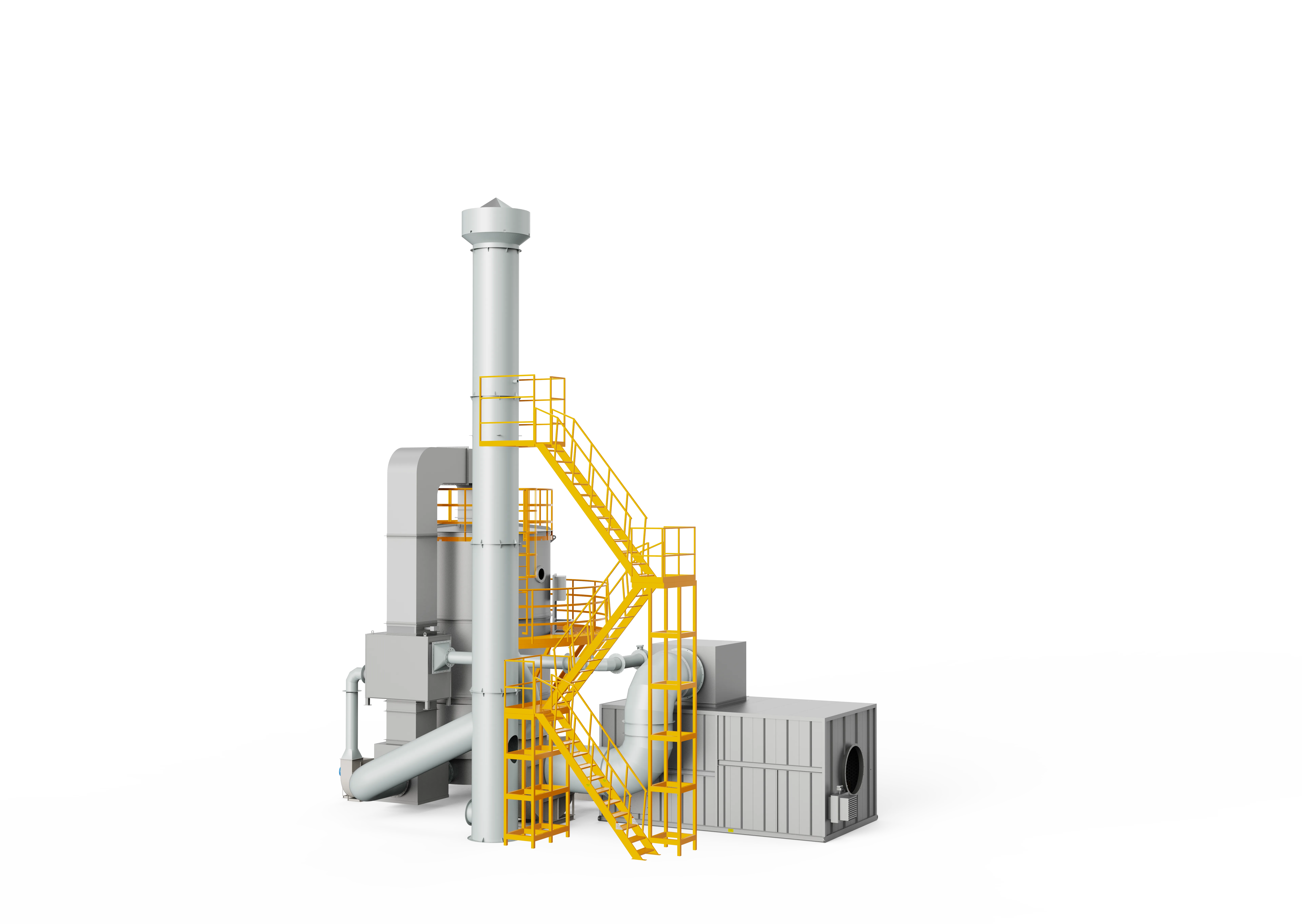
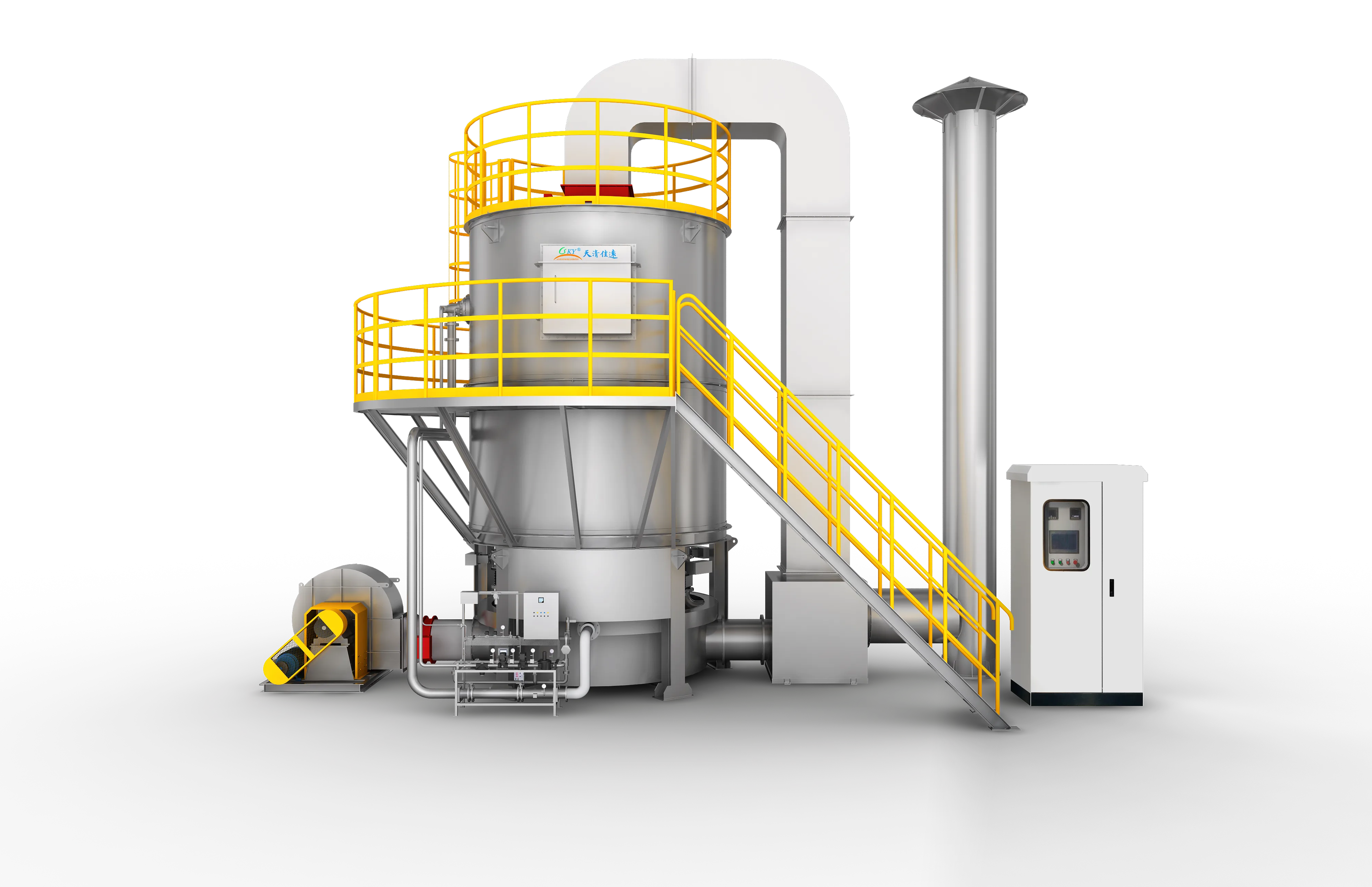
Product images show representative FluxFine configurations. Final dimensions, materials and interfaces follow the approved project design.
Configure Rotor + Rotary RTO for your plant
Share measured process data so the engineering team can confirm suitability, pretreatment, equipment size and scope boundaries.
Source basis: Published values are selection references, not a project guarantee.