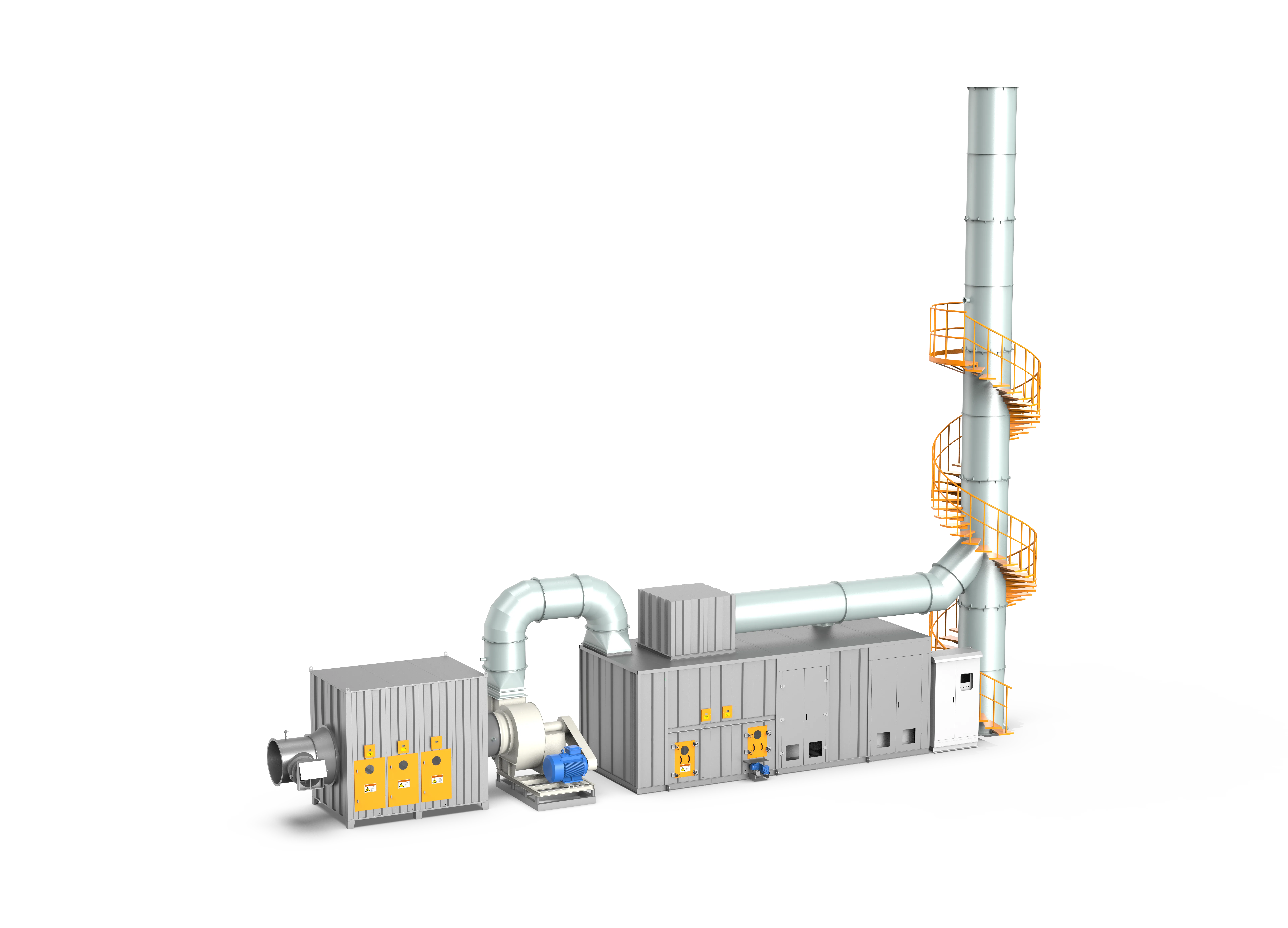
Zeolite Rotor Adsorption & Catalytic Combustion Integrated Machine
A modular, highly compact VOC abatement system integrating zeolite molecular sieve concentration with low-temperature catalytic oxidation (CO) at 250-350°C, delivering energy savings of up to 20%+ and zero fire risk for small-to-medium airflow setups.
Designed around actual process conditions
Designed for factories with small-to-medium airflows and low-concentration organic emissions, the FluxFine Zeolite Rotor Adsorption & Catalytic Combustion (CO) Integrated Machine consolidates gas-enrichment and low-temperature catalytic destruction into a single compact footprint. By avoiding high-temperature direct thermal combustion (RTO) and operating instead at safe, catalytic reaction temperatures (250-350°C / 482-662°F), the system minimizes energy costs and thermal stress. The unit's unified layout simplifies freight and on-site assembly, presenting an exceptionally safe, rapid-install, and compliant abatement option.
ZRTC Series / ZRPC Series / Zeolite Concentration with CO Unit / Integrated Concentrator Catalytic Oxidizer
Maintained consistently under nominal catalytic temperature parameters.
Optimizes system energy consumption, supporting self-sustained catalytic burning.
Vastly safer than direct thermal oxidation (RTO) at 800°C, avoiding mechanical stress.
Operating references and configuration choices
These reference values and modules clarify the scope we evaluate. They are not a substitute for a process-data review or final proposal.
| Engineering reference | Value | How to read it |
|---|---|---|
| Source desorption range | 180–220°C | Catalog reference. |
| Catalytic oxidation range | 250–350°C | Source range for compatible streams; final temperature depends on catalyst and gas chemistry. |
| Application pattern | Low concentration / clean VOCs | Catalyst compatibility is required. |
Typical modules considered
- Dust and mist pretreatment
- Disc or cylindrical zeolite rotor
- Desorption heater and heat-exchange loop
- Catalytic reactor and temperature-control package
- PLC linkage and catalyst-protection monitoring
Project-specific selection notes
- Screen for sulfur, chlorine, silicon, heavy metals and oil that can poison or foul catalyst.
- Confirm the concentrated desorption stream remains within the catalyst and safety operating envelope.
- Plan access for rotor seals, filters and catalyst inspection/replacement.
Zeolite + CO vs. zeolite + RTO
Catalytic oxidation can be attractive for clean, compatible streams and compact layouts. RTO is frequently considered for complex or catalyst-unfriendly solvent mixes. The answer depends on chemistry, concentration variation, heat recovery and site utilities.
- Catalogue cases include low-to-medium concentration coating, printing, injection-moulding and UV-coating applications using adsorption/concentration with catalytic oxidation.
- Case figures need disclosure and engineering review before public use.
What we review before specifying Zeolite Rotor + CO
A product name is a starting point, not a final design. These inputs define pretreatment, materials, controls, equipment size and scope boundaries.
Project data to provide
- VOC species and catalyst-compatibility screening
- Airflow, concentration profile and desired operating cycle
- Sulfur, chlorine, silicon, phosphorus, heavy-metal and aerosol content
- Pretreatment condition and available utilities
- Required emission limit and installation footprint
Typical engineered scope
- Filtration and conditioning matched to catalyst protection
- Catalyst reactor, heater and heat-exchanger configuration
- Optional zeolite or carbon adsorption/concentration stage
- Temperature, pressure and fan controls with safety permissives
- Access for catalyst inspection and planned maintenance
Safety and controls
- Catalyst poison screening is a prerequisite, not an optional upgrade.
- Dust, oil and sticky aerosol must be controlled upstream to protect adsorption media and catalyst surfaces.
- Temperature management and interlocks are configured for the selected catalyst and fuel/heat source.
- No public page should promise a fixed removal rate without the actual gas composition and design basis.
How it works
Raw organic gas undergoes multi-stage dry pre-filtration and flows into the adsorption zone of a zeolite rotor, where organic species are captured within the molecular sieve pores. The clean effluent is vented. The rotating adsorbent carries VOCs into the desorption zone, where a hot stream (180-220°C / 356-428°F) strips the molecules, creating a 10-50x concentrated stream. This small-airflow concentrated gas passes into the CO reactor, preheated by electric elements or gas burner to its ignition threshold (250-300°C / 482-572°F). Over a noble metal (platinum/palladium) catalyst, the VOCs undergo flameless catalytic oxidation, converting completely into CO2 and H2O. The released reaction heat is recycled via an internal heat exchanger to sustain the rotor desorption loop.
- 01Primary, medium, and high-efficiency precision dry filtration to capture dust and aerosols.
- 02Passage of clean process air through the ambient-temperature adsorption sector of the zeolite rotor.
- 03Direct atmosphere discharge of compliant purified gas.
- 04Rotary transfer of saturated adsorbent into the desorption chamber.
- 05Low-temperature thermal desorption using hot air (180-220°C / 356-428°F) to yield a 10-50x concentrated stream.
- 06Preheating of the concentrated gas in the CO heater to ignition temperature (250-300°C / 482-572°F).
- 07Flameless catalytic oxidation over noble metal catalyst beds at 250-350°C, converting VOCs to CO2 and H2O with >=99% purification efficiency.
- 08Counter-flow heat exchange within the CO module to recycle reaction heat into the desorption airflow.
- Small-to-medium airflows (10,000 - 100,000 m³/h) and low-to-medium concentration VOCs.
- Industrial plants requiring rapid installation with minimal on-site structural erection.
- Sectors including paint shops, industrial printing, furniture manufacturing, ink blending, and plastic molding.
- Facilities with restricted space or strict regulations prohibiting open-flame incinerators.
- Inlet air must be strictly dry and dust-free; any particulate deposition on the catalyst will cause masking and permanently destroy its catalytic active sites.
- Strictly prohibit the introduction of silicone, phosphorus, lead, arsenic, high-sulfur, or halogenated compounds which act as permanent catalyst poisons.
- Inlet organic concentration must be closely managed; high organic spikes can lead to uncontrolled exothermic reactions, sintering the catalyst core.
- Periodic catalytic activity checks are recommended; catalyst replacement or regeneration is required when conversion efficiency drops.
Typical pollutants
- Benzene
- Toluene
- Xylene
- Ethyl Acetate
- Butyl Acetate
- Cyclohexanone
- Isopropanol
- Ethanol
- Butanone
- Conventional Solvents
Engineering features
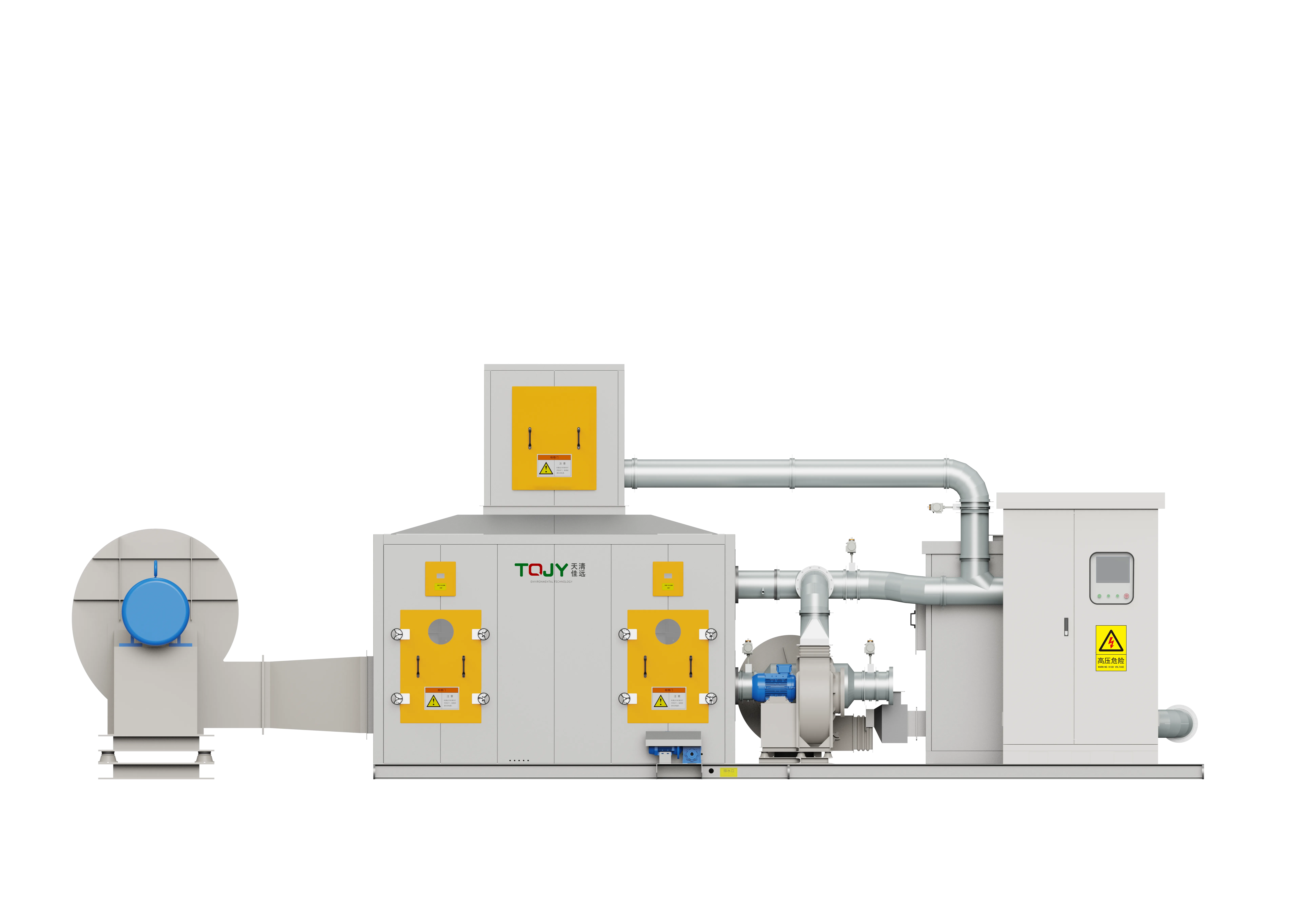
- Modular Integration: Consolidates pre-filtration, rotating concentrator, CO reactor, and heat exchangers into a single, compact structural frame.
- Low Reaction Temperatures: Operates at 250-350°C, eliminating open-flame fire risks and drastically cutting electrical or gas preheating demand.
- Exceptional Destruction Efficiency: Accomplishes total VOC destruction efficiencies of >99% and concentration ratios of 10-50x.
- Highly Customizable Layouts: Supports integrated single-skid shipping, split-level floor configurations, and double-decker space-saving arrangements.
- Comprehensive Safety Chain: Features automated safety interlocks, fan speed protection, temperature regulation dampers, automatic purge loops, and emergency shut-off valves.
- Global Compliance & Safety Standards: Engineered in accordance with NFPA 86 (US) oven/furnace safety standards and CE ATEX directives.
Available options
- TQJY-ZRTC Series: Cylinder modular rotor + CO integrated unit (natural cooling, easy single-module service).
- TQJY-ZRPC Series: Disc rotor + CO integrated unit (integrated 3-zone continuous loop).
- Double-decker space-optimized skid for ultra-tight floor plans.
- Integrated online FID gas analyzer with remote cloud monitoring.
Relevant industries
Printing & Laminating
Gravure, flexible packaging, lamination, optical film and continuous web processes.
Coating & Surface Finishing
Industrial paint, UV coating, adhesive, metal finishing and multi-booth surface processes.
Automotive & E-Mobility
OEM parts, e-bike, and industrial spray booth exhaust.
Electronics, PCB & Semiconductors
PCB, semiconductor, motor, and appliance process exhaust.
Rubber & Plastics
PVC, compounding, injection, and polymer processing fumes.
Pharmaceutical & Medical
Solvent exhaust from synthesis, coating, and finishing.
New Materials & New Energy
Battery materials, functional films, composites and advanced material production.
General technology selection
These answers explain the selection path. Final performance, safety scope and dimensions follow the approved project design.
Why choose catalytic oxidation?
Catalytic oxidation can operate at a lower reaction temperature than thermal-only oxidation for compatible, clean VOC streams. It is commonly considered where compact layout or lower-temperature operation is valuable.
What can damage a catalyst?
Sulfur, chlorine, silicon, heavy metals, dust, oil and some reactive compounds can reduce catalyst activity. The process chemistry and upstream controls must be reviewed first.
Source basis: VOCs equipment source. Catalyst performance and service interval depend on gas chemistry and pretreatment.
Specific product Q&A
Why combine a zeolite rotor with catalytic combustion instead of an RTO?
A Zeolite Rotor + Catalytic Combustion (CO) system is ideal for high-volume, low-concentration exhaust when natural gas is unavailable or highly restricted. Unlike an RTO, which requires high temperatures (800°C) and typically natural gas burners, a CO unit oxidizes VOCs at a much lower temperature (280-350°C) using noble metal catalysts. This lower temperature allows the entire system, including the rotor's desorption loop, to be powered entirely by electric heaters, making it the perfect solution for zero-emission or all-electric manufacturing facilities.
What is the desorption temperature for a zeolite rotor in a CO system?
The standard desorption temperature for a hydrophobic zeolite rotor is 180°C to 220°C. In a Zeolite + CO system, the concentrated VOC stream exits the rotor, gets pre-heated, and is destroyed in the catalytic chamber at ~300°C. The hot purified gas exiting the catalyst is then passed through an internal heat exchanger to heat the incoming fresh desorption air up to that required 180-220°C threshold, creating an exceptionally energy-efficient closed loop.
How to handle high-boiling point VOCs in a zeolite rotor?
High-boiling point VOCs (typically >200°C) are notoriously difficult to desorb and will slowly accumulate within the zeolite pores, permanently blinding the rotor. To handle this, FluxFine implements a specialized high-temperature regeneration cycle (washing). By temporarily bypassing the standard controls and elevating the desorption temperature to 250-300°C during offline maintenance, these stubborn heavy hydrocarbons are forced out of the molecular sieve, restoring the rotor's adsorption capacity.
Equipment views
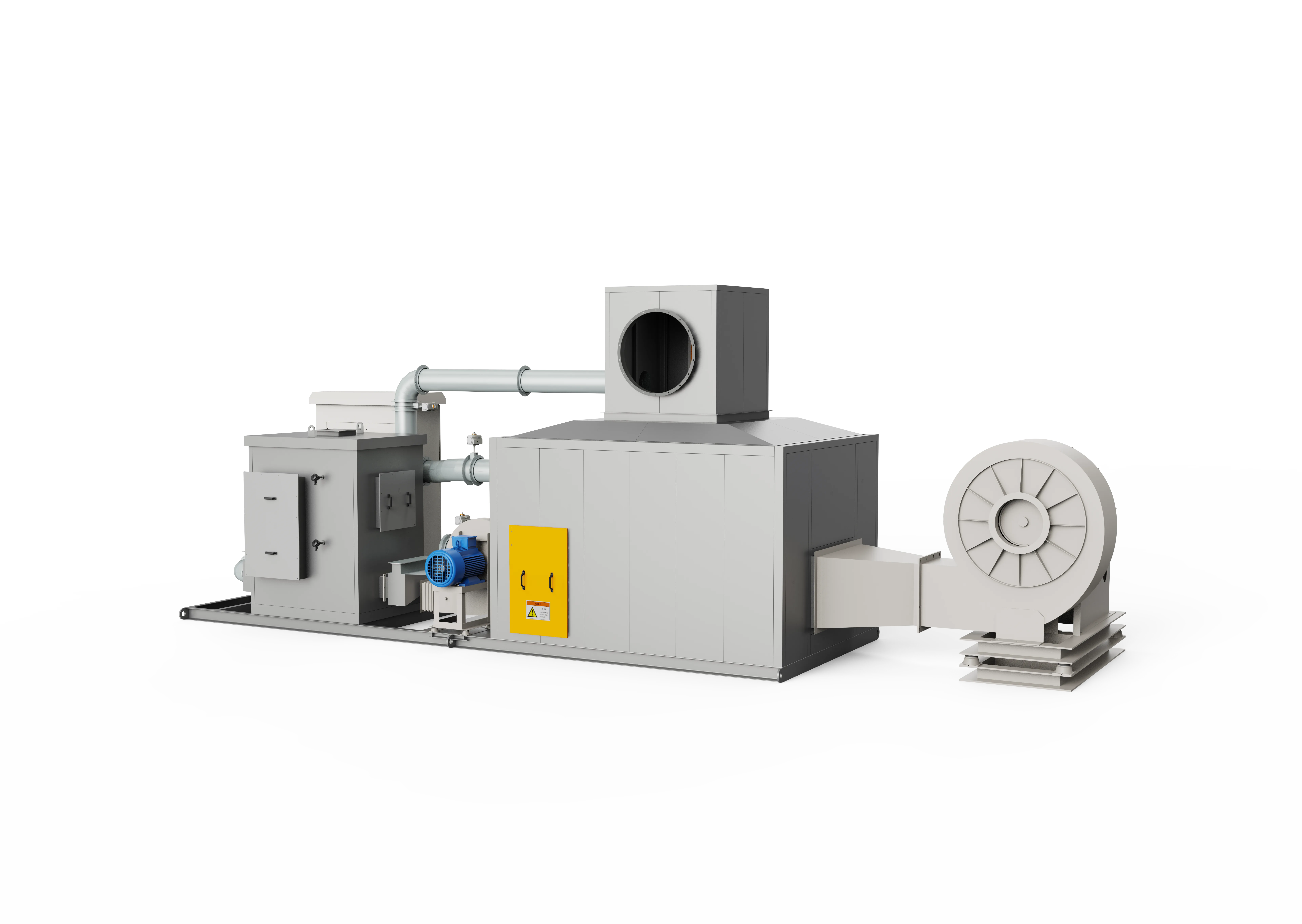
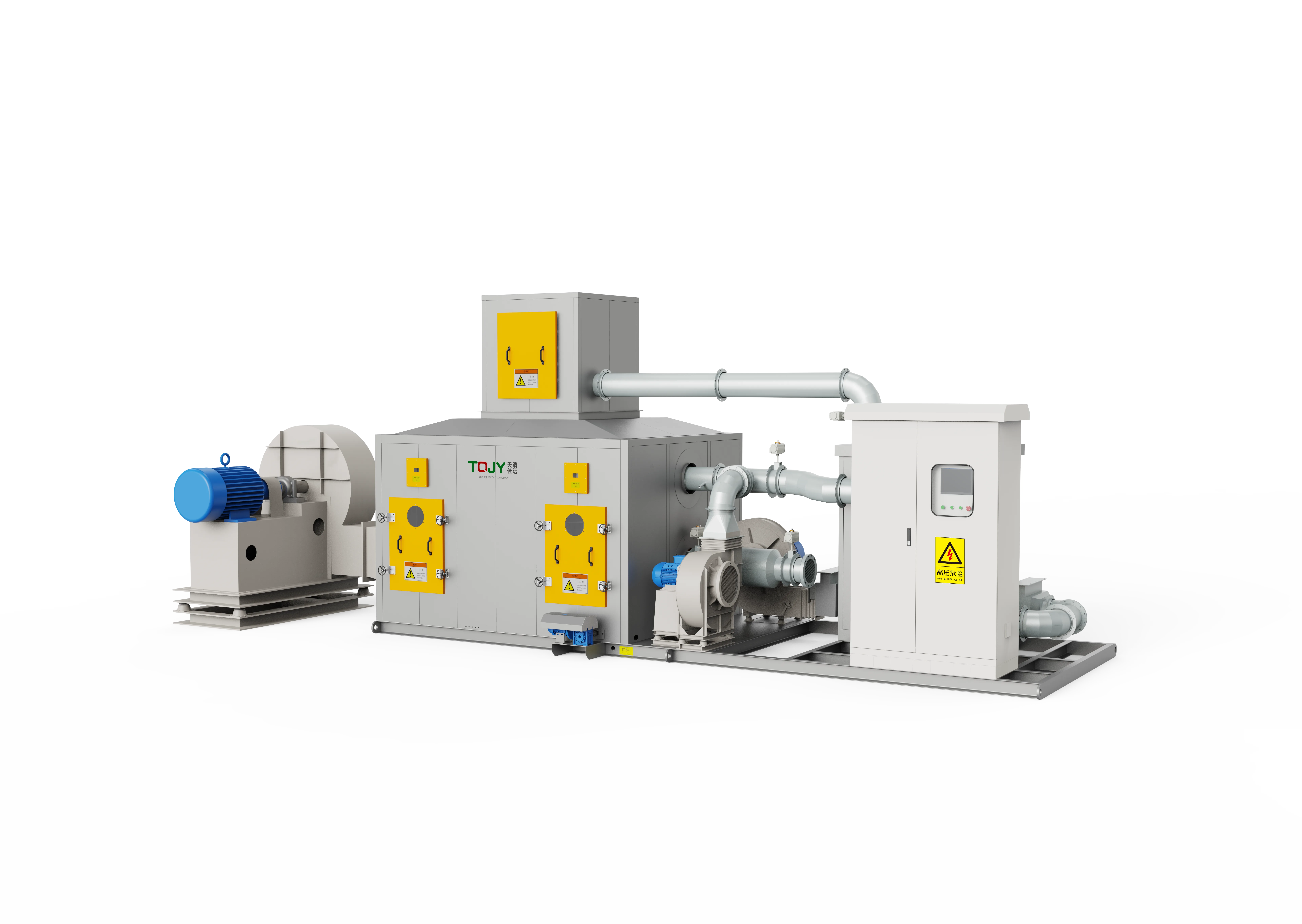
Product images show representative FluxFine configurations. Final dimensions, materials and interfaces follow the approved project design.
Technical Parameters
Detailed parameter models for engineering selection and sizing. Note that dimensions and efficiencies are for reference under nominal conditions.
| Model | Airflow (m³/h) | Inlet VOCs (mg/m³) | Efficiency | Filter Type | Desorption Air (m³/h) | Desorption Temp | Ads. Fan Power | Des. Fan Power | Gas Power | Electric Power | Dimensions (m) |
|---|---|---|---|---|---|---|---|---|---|---|---|
| Cylindrical Rotor Models | |||||||||||
| TQJY-ZRTC-10L | 10000 | <=150 | 90% | G4+F7+F9 | 1000-1500 | 180-220 | 15 | 5.5 | 100,000 kcal/h (116 kW / 0.4 MMBtu/hr) | 75 kW | Modular / Site Dependent |
| TQJY-ZRTC-10M | 10000 | <=350 | 91% | G4+F7+F9 | 1000-1500 | 180-220 | 15 | 5.5 | 100,000 kcal/h (116 kW / 0.4 MMBtu/hr) | 75 kW | Modular / Site Dependent |
| TQJY-ZRTC-10 | 10000 | <=600 | 93% | G4+F7+F9 | 1000-1500 | 180-220 | 15 | 5.5 | 100,000 kcal/h (116 kW / 0.4 MMBtu/hr) | 75 kW | Modular / Site Dependent |
| TQJY-ZRTC-20L | 20000 | <=150 | 90% | G4+F7+F9 | 1000-1500 | 180-220 | 30 | 5.5 | 100,000 kcal/h (116 kW / 0.4 MMBtu/hr) | 75 kW | Modular / Site Dependent |
| TQJY-ZRTC-20M | 20000 | <=350 | 91% | G4+F7+F9 | 1000-2000 | 180-220 | 30 | 5.5 | 100,000 kcal/h (116 kW / 0.4 MMBtu/hr) | 75 kW | Modular / Site Dependent |
| TQJY-ZRTC-20 | 20000 | <=600 | 93% | G4+F7+F9 | 1500-2500 | 180-220 | 30 | 7.5 | 100,000 kcal/h (116 kW / 0.4 MMBtu/hr) | 105 kW | Modular / Site Dependent |
| TQJY-ZRTC-30L | 30000 | <=150 | 90% | G4+F7+F9 | 1000-2000 | 180-220 | 45 | 5.5 | 100,000 kcal/h (116 kW / 0.4 MMBtu/hr) | 75 kW | Modular / Site Dependent |
| TQJY-ZRTC-30M | 30000 | <=350 | 91% | G4+F7+F9 | 1500-2500 | 180-220 | 45 | 7.5 | 100,000 kcal/h (116 kW / 0.4 MMBtu/hr) | 105 kW | Modular / Site Dependent |
| TQJY-ZRTC-30 | 30000 | <=600 | 93% | G4+F7+F9 | 1800-3500 | 180-220 | 45 | 11 | 100,000 kcal/h (116 kW / 0.4 MMBtu/hr) | 120 kW | Modular / Site Dependent |
| TQJY-ZRTC-40L | 40000 | <=150 | 90% | G4+F7+F9 | 1500-3000 | 180-220 | 55 | 11 | 100,000 kcal/h (116 kW / 0.4 MMBtu/hr) | 105 kW | Modular / Site Dependent |
| TQJY-ZRTC-40M | 40000 | <=350 | 91% | G4+F7+F9 | 1800-3500 | 180-220 | 55 | 11 | 100,000 kcal/h (116 kW / 0.4 MMBtu/hr) | 120 kW | Modular / Site Dependent |
| TQJY-ZRTC-40 | 40000 | <=600 | 93% | G4+F7+F9 | 1800-4000 | 180-220 | 55 | 11 | 100,000 kcal/h (116 kW / 0.4 MMBtu/hr) | 120 kW | Modular / Site Dependent |
| TQJY-ZRTC-50L | 50000 | <=150 | 90% | G4+F7+F9 | 1500-3000 | 180-220 | 75 | 11 | 100,000 kcal/h (116 kW / 0.4 MMBtu/hr) | 105 kW | Modular / Site Dependent |
| TQJY-ZRTC-50M | 50000 | <=350 | 91% | G4+F7+F9 | 1800-3500 | 180-220 | 75 | 11 | 100,000 kcal/h (116 kW / 0.4 MMBtu/hr) | 120 kW | Modular / Site Dependent |
| TQJY-ZRTC-50 | 50000 | <=600 | 93% | G4+F7+F9 | 2200-5000 | 180-220 | 75 | 15 | 150,000 kcal/h (174 kW / 0.6 MMBtu/hr) | 144 kW | Modular / Site Dependent |
| TQJY-ZRTC-60L | 60000 | <=150 | 90% | G4+F7+F9 | 1800-3500 | 180-220 | 90 | 11 | 100,000 kcal/h (116 kW / 0.4 MMBtu/hr) | 120 kW | Modular / Site Dependent |
| TQJY-ZRTC-60M | 60000 | <=350 | 91% | G4+F7+F9 | 2200-4500 | 180-220 | 90 | 15 | 150,000 kcal/h (174 kW / 0.6 MMBtu/hr) | 144 kW | Modular / Site Dependent |
| TQJY-ZRTC-60 | 60000 | <=600 | 93% | G4+F7+F9 | 2700-6000 | 180-220 | 90 | 15 | 150,000 kcal/h (174 kW / 0.6 MMBtu/hr) | 156 kW | Modular / Site Dependent |
| TQJY-ZRTC-70L | 70000 | <=150 | 90% | G4+F7+F9 | 1800-4000 | 180-220 | 110 | 11 | 100,000 kcal/h (116 kW / 0.4 MMBtu/hr) | 120 kW | Modular / Site Dependent |
| TQJY-ZRTC-70M | 70000 | <=350 | 91% | G4+F7+F9 | 2200-5000 | 180-220 | 110 | 15 | 150,000 kcal/h (174 kW / 0.6 MMBtu/hr) | 144 kW | Modular / Site Dependent |
| TQJY-ZRTC-70 | 70000 | <=600 | 93% | G4+F7+F9 | 3200-7000 | 180-220 | 110 | 18.5 | 150,000 kcal/h (174 kW / 0.6 MMBtu/hr) | 168 kW | Modular / Site Dependent |
| TQJY-ZRTC-80L | 80000 | <=150 | 90% | G4+F7+F9 | 2200-4500 | 180-220 | 110 | 15 | 150,000 kcal/h (174 kW / 0.6 MMBtu/hr) | 144 kW | Modular / Site Dependent |
| TQJY-ZRTC-80M | 80000 | <=350 | 91% | G4+F7+F9 | 2700-5500 | 180-220 | 110 | 15 | 150,000 kcal/h (174 kW / 0.6 MMBtu/hr) | 156 kW | Modular / Site Dependent |
| TQJY-ZRTC-80 | 80000 | <=600 | 93% | G4+F7+F9 | 3600-8000 | 180-220 | 110 | 18.5 | 200,000 kcal/h (232 kW / 0.8 MMBtu/hr) | 180 kW | Modular / Site Dependent |
| TQJY-ZRTC-90L | 90000 | <=150 | 90% | G4+F7+F9 | 2200-5000 | 180-220 | 132 | 15 | 150,000 kcal/h (174 kW / 0.6 MMBtu/hr) | 144 kW | Modular / Site Dependent |
| TQJY-ZRTC-90M | 90000 | <=350 | 91% | G4+F7+F9 | 3200-6500 | 180-220 | 132 | 18.5 | 150,000 kcal/h (174 kW / 0.6 MMBtu/hr) | 168 kW | Modular / Site Dependent |
| TQJY-ZRTC-90 | 90000 | <=600 | 93% | G4+F7+F9 | 4000-9000 | 180-220 | 132 | 22 | 200,000 kcal/h (232 kW / 0.8 MMBtu/hr) | 210 kW | Modular / Site Dependent |
| TQJY-ZRTC-100L | 100000 | <=150 | 90% | G4+F7+F9 | 2700-5500 | 180-220 | 132 | 15 | 150,000 kcal/h (174 kW / 0.6 MMBtu/hr) | 156 kW | Modular / Site Dependent |
| TQJY-ZRTC-100M | 100000 | <=350 | 91% | G4+F7+F9 | 3200-7000 | 180-220 | 132 | 18.5 | 150,000 kcal/h (174 kW / 0.6 MMBtu/hr) | 168 kW | Modular / Site Dependent |
| TQJY-ZRTC-100 | 100000 | <=600 | 93% | G4+F7+F9 | 4800-10000 | 180-220 | 132 | 22 | 250,000 kcal/h (290 kW / 1.0 MMBtu/hr) | 240 kW | Modular / Site Dependent |
| Disc Rotor Models | |||||||||||
| TQJY-ZRPC-10M | 10000 | <=400 | 91% | G4+F7+F9 | 1000-1500 | 180-220 | 15 | 5.5 | 100,000 kcal/h (116 kW / 0.4 MMBtu/hr) | 75 kW | Modular / Site Dependent |
| TQJY-ZRPC-10 | 10000 | <=600 | 93% | G4+F7+F9 | 1000-1500 | 180-220 | 15 | 5.5 | 100,000 kcal/h (116 kW / 0.4 MMBtu/hr) | 75 kW | Modular / Site Dependent |
| TQJY-ZRPC-10H | 10000 | <=800 | 95% | G4+F7+F9 | 1000-2000 | 180-220 | 15 | 5.5 | 100,000 kcal/h (116 kW / 0.4 MMBtu/hr) | 75 kW | Modular / Site Dependent |
| TQJY-ZRPC-10U | 10000 | <=1000 | 95% | G4+F7+F9 | 1500-2500 | 180-220 | 15 | 7.5 | 100,000 kcal/h (116 kW / 0.4 MMBtu/hr) | 105 kW | Modular / Site Dependent |
| TQJY-ZRPC-15M | 15000 | <=400 | 91% | G4+F7+F9 | 1000-1500 | 180-220 | 15 | 5.5 | 100,000 kcal/h (116 kW / 0.4 MMBtu/hr) | 75 kW | Modular / Site Dependent |
| TQJY-ZRPC-15 | 15000 | <=600 | 93% | G4+F7+F9 | 1500-2000 | 180-220 | 15 | 5.5 | 100,000 kcal/h (116 kW / 0.4 MMBtu/hr) | 75 kW | Modular / Site Dependent |
| TQJY-ZRPC-15H | 15000 | <=800 | 95% | G4+F7+F9 | 1500-2500 | 180-220 | 15 | 7.5 | 100,000 kcal/h (116 kW / 0.4 MMBtu/hr) | 105 kW | Modular / Site Dependent |
| TQJY-ZRPC-15U | 15000 | <=1000 | 95% | G4+F7+F9 | 1500-3000 | 180-220 | 15 | 11 | 100,000 kcal/h (116 kW / 0.4 MMBtu/hr) | 105 kW | Modular / Site Dependent |
| TQJY-ZRPC-20M | 20000 | <=400 | 91% | G4+F7+F9 | 1000-2000 | 180-220 | 30 | 5.5 | 100,000 kcal/h (116 kW / 0.4 MMBtu/hr) | 75 kW | Modular / Site Dependent |
| TQJY-ZRPC-20 | 20000 | <=600 | 93% | G4+F7+F9 | 1500-2500 | 180-220 | 30 | 7.5 | 100,000 kcal/h (116 kW / 0.4 MMBtu/hr) | 105 kW | Modular / Site Dependent |
| TQJY-ZRPC-20H | 20000 | <=800 | 95% | G4+F7+F9 | 1500-3000 | 180-220 | 30 | 11 | 100,000 kcal/h (116 kW / 0.4 MMBtu/hr) | 105 kW | Modular / Site Dependent |
| TQJY-ZRPC-20U | 20000 | <=1000 | 95% | G4+F7+F9 | 1800-3500 | 180-220 | 30 | 11 | 100,000 kcal/h (116 kW / 0.4 MMBtu/hr) | 120 kW | Modular / Site Dependent |
| TQJY-ZRPC-30M | 30000 | <=400 | 91% | G4+F7+F9 | 1500-2500 | 180-220 | 45 | 7.5 | 100,000 kcal/h (116 kW / 0.4 MMBtu/hr) | 105 kW | Modular / Site Dependent |
| TQJY-ZRPC-30 | 30000 | <=600 | 93% | G4+F7+F9 | 1800-3500 | 180-220 | 45 | 11 | 100,000 kcal/h (116 kW / 0.4 MMBtu/hr) | 120 kW | Modular / Site Dependent |
| TQJY-ZRPC-30H | 30000 | <=800 | 95% | G4+F7+F9 | 2200-4500 | 180-220 | 45 | 15 | 150,000 kcal/h (174 kW / 0.6 MMBtu/hr) | 144 kW | Modular / Site Dependent |
| TQJY-ZRPC-30U | 30000 | <=1000 | 95% | G4+F7+F9 | 2200-5000 | 180-220 | 45 | 15 | 150,000 kcal/h (174 kW / 0.6 MMBtu/hr) | 144 kW | Modular / Site Dependent |
| TQJY-ZRPC-40M | 40000 | <=400 | 91% | G4+F7+F9 | 1500-3000 | 180-220 | 55 | 11 | 100,000 kcal/h (116 kW / 0.4 MMBtu/hr) | 105 kW | Modular / Site Dependent |
| TQJY-ZRPC-40 | 40000 | <=600 | 93% | G4+F7+F9 | 1800-4000 | 180-220 | 55 | 11 | 100,000 kcal/h (116 kW / 0.4 MMBtu/hr) | 120 kW | Modular / Site Dependent |
| TQJY-ZRPC-40H | 40000 | <=800 | 95% | G4+F7+F9 | 2700-5500 | 180-220 | 55 | 15 | 150,000 kcal/h (174 kW / 0.6 MMBtu/hr) | 156 kW | Modular / Site Dependent |
| TQJY-ZRPC-40U | 40000 | <=1000 | 95% | G4+F7+F9 | 2700-7000 | 180-220 | 55 | 18.5 | 150,000 kcal/h (174 kW / 0.6 MMBtu/hr) | 168 kW | Modular / Site Dependent |
| TQJY-ZRPC-50M | 50000 | <=400 | 91% | G4+F7+F9 | 1800-4000 | 180-220 | 75 | 11 | 100,000 kcal/h (116 kW / 0.4 MMBtu/hr) | 120 kW | Modular / Site Dependent |
| TQJY-ZRPC-50 | 50000 | <=600 | 93% | G4+F7+F9 | 2200-5000 | 180-220 | 75 | 15 | 150,000 kcal/h (174 kW / 0.6 MMBtu/hr) | 144 kW | Modular / Site Dependent |
| TQJY-ZRPC-50H | 50000 | <=800 | 95% | G4+F7+F9 | 2700-7000 | 180-220 | 75 | 18.5 | 150,000 kcal/h (174 kW / 0.6 MMBtu/hr) | 168 kW | Modular / Site Dependent |
| TQJY-ZRPC-50U | 50000 | <=1000 | 95% | G4+F7+F9 | 4000-8500 | 180-220 | 75 | 22 | 200,000 kcal/h (232 kW / 0.8 MMBtu/hr) | 210 kW | Modular / Site Dependent |
| TQJY-ZRPC-60M | 60000 | <=400 | 91% | G4+F7+F9 | 2200-5000 | 180-220 | 90 | 15 | 150,000 kcal/h (174 kW / 0.6 MMBtu/hr) | 144 kW | Modular / Site Dependent |
| TQJY-ZRPC-60 | 60000 | <=600 | 93% | G4+F7+F9 | 2700-6000 | 180-220 | 90 | 15 | 150,000 kcal/h (174 kW / 0.6 MMBtu/hr) | 156 kW | Modular / Site Dependent |
| TQJY-ZRPC-60H | 60000 | <=800 | 95% | G4+F7+F9 | 3600-8000 | 180-220 | 90 | 22 | 200,000 kcal/h (232 kW / 0.8 MMBtu/hr) | 180 kW | Modular / Site Dependent |
| TQJY-ZRPC-60U | 60000 | <=1000 | 95% | G4+F7+F9 | 4800-10000 | 180-220 | 90 | 22 | 250,000 kcal/h (290 kW / 1.0 MMBtu/hr) | 180 kW | Modular / Site Dependent |
| TQJY-ZRPC-70M | 70000 | <=400 | 91% | G4+F7+F9 | 2700-5500 | 180-220 | 110 | 15 | 150,000 kcal/h (174 kW / 0.6 MMBtu/hr) | 156 kW | Modular / Site Dependent |
| TQJY-ZRPC-70 | 70000 | <=600 | 93% | G4+F7+F9 | 3200-7000 | 180-220 | 110 | 18.5 | 150,000 kcal/h (174 kW / 0.6 MMBtu/hr) | 168 kW | Modular / Site Dependent |
| TQJY-ZRPC-80M | 80000 | <=400 | 91% | G4+F7+F9 | 2700-5500 | 180-220 | 110 | 15 | 150,000 kcal/h (174 kW / 0.6 MMBtu/hr) | 156 kW | Modular / Site Dependent |
Proven Zeolite Rotor + CO installations
Review documented treatment trains featuring Zeolite Rotor + CO technology across various industrial processes.
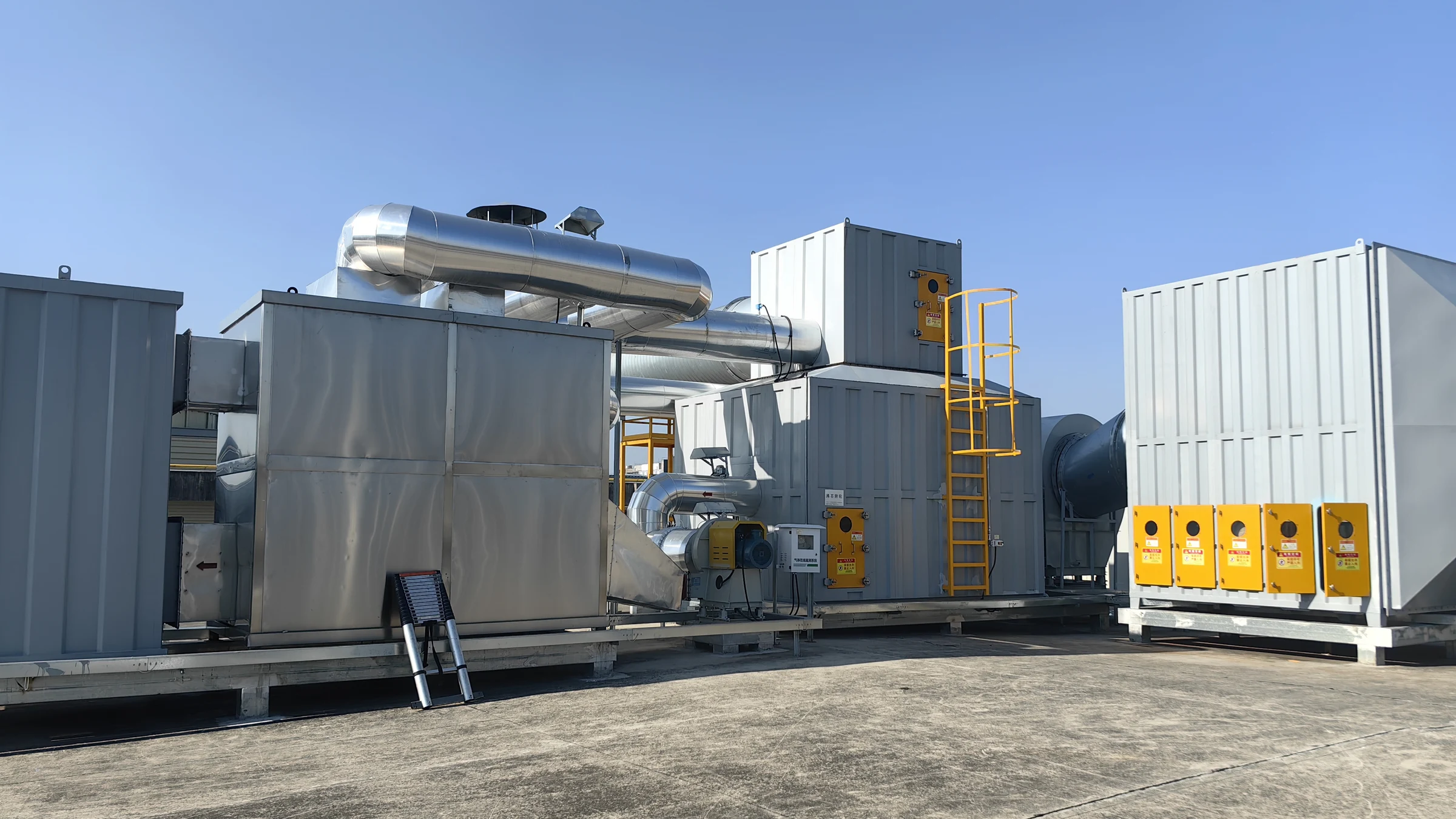
170,000 m³/h (100,000 CFM) · Glass spray-painting and silk-screening
170,000 m³/h VOC Abatement System for Glass Spray-Painting and Silk-Screening
Multi-Stage Dry Filtration (G4-F9) + Cylinder Zeolite Rotor + Catalytic Oxidizer (CO)
Read project reference →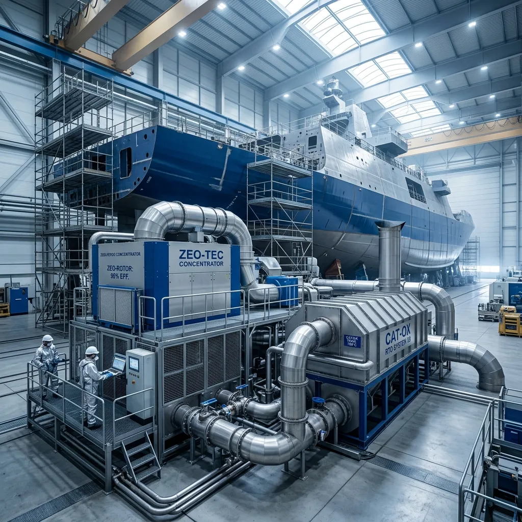
35,000 m³/h (20,600 CFM) · Shipbuilding (Painting & Curing Processes)
High-Efficiency VOC Abatement for Shipbuilding Paint Facilities
Multi-stage Dry Filtration + Cylindrical Zeolite Concentrator + Catalytic Oxidation (CO)
Read project reference →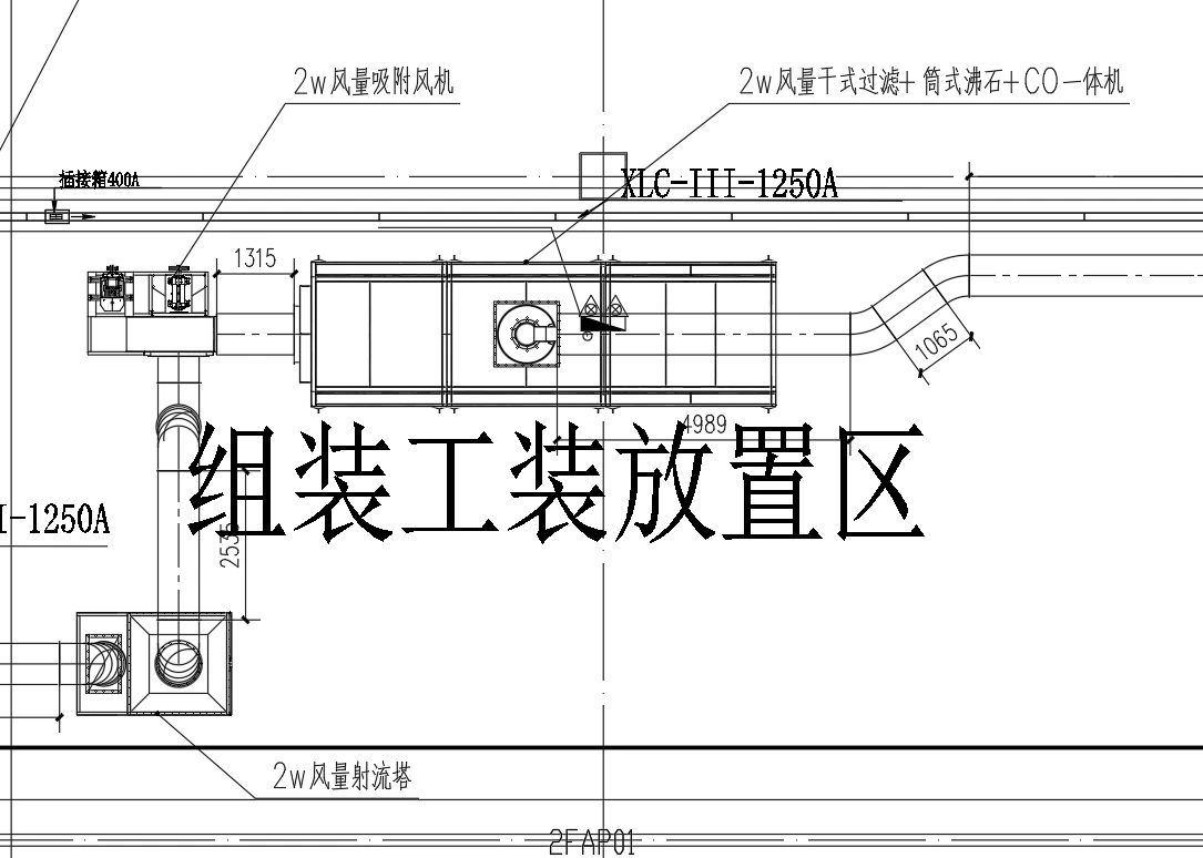
20,000 m³/h (11,760 CFM) · Automated automotive LED headlamp and adaptive front-lighting (AFS) robotic color coating & UV curing
20,000 m³/h Automotive Headlamp Coating VOCs & Paint Mist Abatement System for Jiali Car Light
Jet Kinetic Scrubber (Auto Slag Skimmer) + 5-Stage Spring-Clip Modular Dry Filter + Cylindrical Zeolite Drum & CO Skid (13.3:1 Ratio)
Read project reference →Configure Zeolite Rotor + CO for your plant
Share measured process data so the engineering team can confirm suitability, pretreatment, equipment size and scope boundaries.
Source basis: Published values are selection references, not a project guarantee.