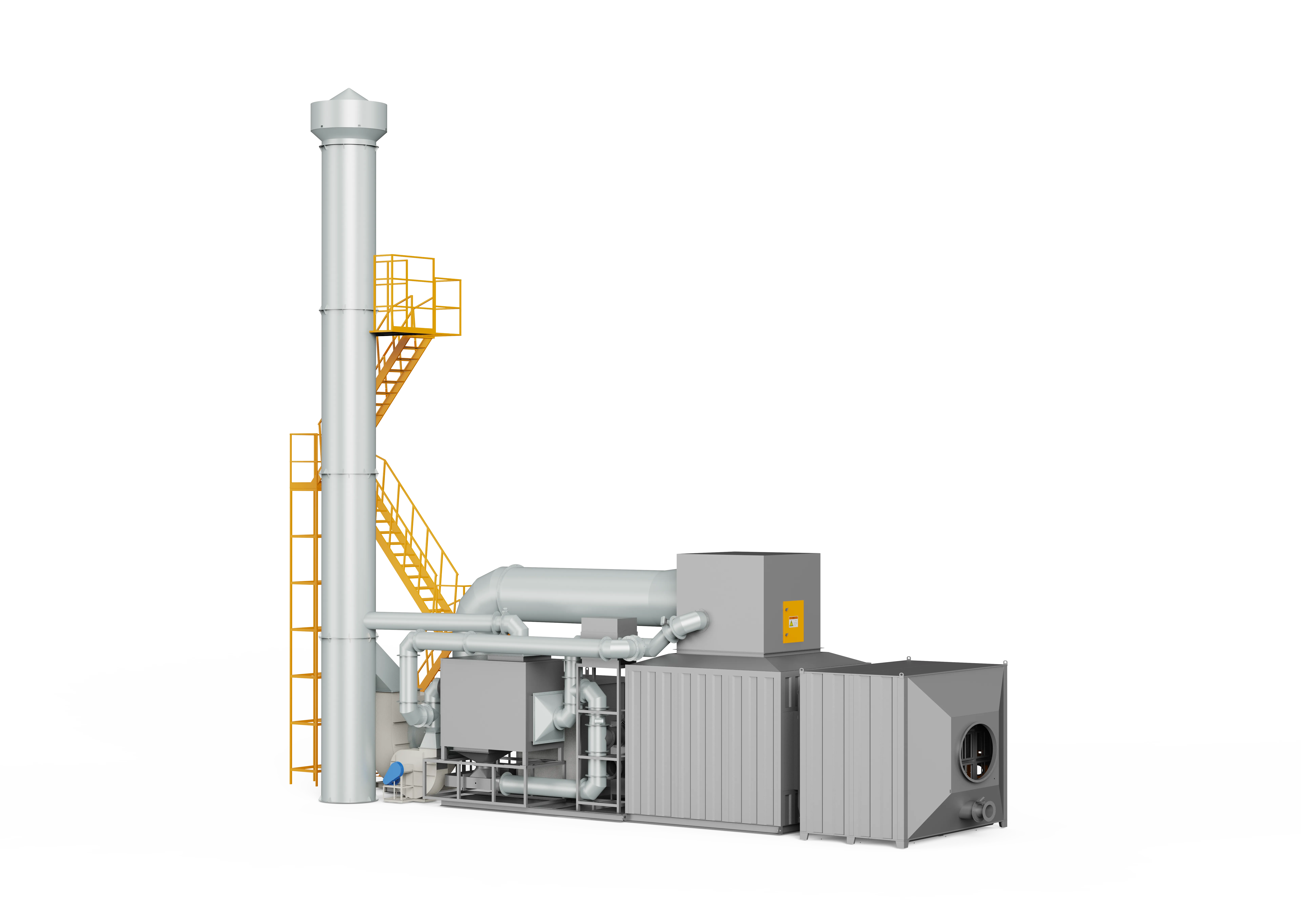
Zeolite Rotor Concentrator
A high-efficiency VOC pre-treatment and concentration system utilizing advanced hydrophobic zeolite molecular sieves to continuously adsorb, desorb, and enrich large-airflow, low-concentration organic exhaust gases, reducing downstream thermal destruction energy consumption by 40% to over 50%.
Designed around actual process conditions
Engineered for high-volume industrial VOC abatement, the FluxFine Zeolite Rotor Concentrator represents the pinnacle of gas-enrichment pre-treatment technology. Utilizing highly hydrophobic, in-house manufactured molecular sieves, the system partitions continuously rotating active media into functional zones to upgrade low-concentration organic streams into highly concentrated, low-volume process air. By minimizing the scale and energy load of downstream oxidizers (such as RTO or CO units), it ensures stable compliance with ultra-low emission standards while delivering excellent lifecycle cost optimization for modern industrial plants.
Zeolite Concentration Wheel / Molecular Sieve Rotor / VOC Concentrator / Rotary Adsorber / VOC Concentrator Wheel
Highly dependent on inlet VOC concentrations and species; lower initial concentration allows for higher ratios.
Cylinder rotor configurations achieve 90-95% efficiency, while Disc rotor configurations reach 95-97% under nominal parameters.
Enrichment reduces downstream thermal treatment airflow, significantly cutting fuel or electricity consumption for oxidation.
Operating references and configuration choices
These reference values and modules clarify the scope we evaluate. They are not a substitute for a process-data review or final proposal.
| Engineering reference | Value | How to read it |
|---|---|---|
| Source inlet temperature | ≤40°C | Source guidance before the rotor; confirm for the actual media and pretreatment. |
| Source relative humidity | ≤80% | Reference intake condition; humidity effects require engineering review. |
| Desorption temperature | 180–220°C | Catalog reference. |
| Concentration ratio | 10–40x | Reference range; VOC chemistry, load and rotor selection affect result. |
Typical modules considered
- G4/F6/F9-style or equivalent staged dry filtration selected to duty
- Disc or cylindrical molecular-sieve rotor
- Desorption-air heater and cooling arrangement
- Rotor seal, drive and differential-pressure monitoring
- Connection to RTO or catalytic oxidation stage
Project-specific selection notes
- Carry out a compound-by-compound compatibility review, particularly for high-boiling, reactive, low-boiling or highly polar substances.
- Set pretreatment around dust, paint mist, oil/tar aerosol and corrosive gas removal.
- Assess whether integrated, split or vertical arrangement gives the safest maintenance access and duct routing.
Zeolite rotor vs. activated carbon
Zeolite concentration is often evaluated for large, dilute, compatible VOC streams and continuous operation. Activated carbon may be considered for different airflow, duty-cycle or recovery requirements. Media compatibility, humidity, fire risk and regeneration method are decisive.
- The catalogue and equipment source provide reference rotor tables across multiple airflow and concentration bands.
- These tables are sizing references, not a web quotation or universal performance schedule.
What we review before specifying Zeolite Rotor
A product name is a starting point, not a final design. These inputs define pretreatment, materials, controls, equipment size and scope boundaries.
Project data to provide
- Airflow and concentration profile by production mode
- VOC component list, boiling point and polymerization risk
- Inlet temperature, relative humidity, dust and paint-mist loading
- Desorption heat source and downstream oxidizer selection
- Available footprint for integrated, split or vertical layout
Typical engineered scope
- Multi-stage dry filtration or other approved pretreatment
- Disc or cylindrical molecular-sieve rotor
- Desorption-air heater, cooling section and variable-speed drives
- Downstream RTO or catalytic oxidizer connection
- PLC linkage, differential-pressure and temperature monitoring
Safety and controls
- Rotor media compatibility is confirmed before equipment selection.
- Dust, paint mist, acid/alkali gases and high-boiling or polymerizable compounds require removal or dedicated review.
- Desorption temperature, airflow and downstream oxidizer load are controlled as one system.
- A compatibility assessment is required for low-boiling, highly polar and corrosive compounds.
How it works
The system operates on continuous temperature and pressure swing adsorption-desorption cycles. Pre-filtered raw VOC gas passes through the adsorption sector of the rotor under ambient conditions, where organic molecules are efficiently trapped in the high-density micropores of the hydrophobic zeolite media. The purified clean air is then directly discharged. As the rotor turns slowly (1-6 r/h), the saturated sector rotates into the desorption zone, where it is swept by a low-volume, high-temperature hot air stream (180-220°C / 356-428°F). This thermal energy breaks the adsorption bonds, releasing the VOCs into a concentrated, low-airflow gas stream (10-100x concentration ratio) routed to downstream incinerators. For disc rotors, the sector is cooled via a clean cooling zone to restore capacity; cylindrical rotors leverage high specific surface areas for natural cooling, completing the continuous loop.
- 01Exhaust collection and multi-stage precision dry dust filtration (typically G4+F6+F9 or G4+F7+F9) to remove particulates and aerosols.
- 02Continuous adsorption of gas-phase VOCs at ambient temperature through the microporous structures of the rotating hydrophobic molecular sieve.
- 03Direct and compliant discharge of the purified, clean gas stream into the atmosphere.
- 04Slow, automated rotary indexing (1-6 r/h) of the saturated zeolite sector into the sealed desorption chamber.
- 05High-temperature thermal desorption and regeneration using hot air (180-220°C / 356-428°F), converting low-concentration gas into a 10-100x enriched, high-concentration stream.
- 06Piping of the highly concentrated VOC gas stream to downstream thermal oxidizers (RTO/CO) for complete destructive oxidation.
- 07Cooling of the regenerated sector to ambient temperature (via dedicated cold-air sweeping or natural heat dissipation) to restore high-affinity adsorption capacity.
- Large-airflow, low-concentration industrial organic waste gas treatment (concentration ratio 15-100x).
- Removal of conventional organic solvents including benzene series, esters, ketones, alcohols, aldehydes, and mixed VOCs.
- High-volume manufacturing processes such as automotive painting, semiconductor manufacturing, flexible packaging printing, industrial coating, pharmaceutical, and chemical synthesis.
- Complex industrial environments characterized by irregular operating shifts, variable exhaust airflows, and fluctuating pollutant concentration profiles.
- Inlet process gas temperature must be strictly controlled at <= 40°C; relative humidity must be <= 80% (pre-treatment cooling and dehumidification is mandatory if relative humidity exceeds 70%).
- Strict particulate and dust limitation: Inlet particulate matter must be pre-filtered to < 1 mg/m³ to prevent irreversible physical clogging of the zeolite micropores.
- Strict paint mist restriction: Resin-based aerosols, mist-like liquids, and paint droplets must be pre-treated to < 0.1 mg/m³.
- Acidic gases (HCl, Cl2, SO2, H2S, NOx, NH3) must be removed in wet scrubbers or dry media to maintain pH 4-10, avoiding chemical corrosion of the rotor skeleton.
- Strict content limits on polymerizable monomers (such as acrylic acid/esters, acrylonitrile, butadiene) and active compounds (isocyanates, silane coupling agents) to prevent catalyst/adsorbent deactivation (< 0.1 mg/m³; styrene is limited to < 600 mg/m³).
- Organic compounds with boiling points > 220°C (e.g., diethylene glycol butyl ether, triethanolamine, phthalate plasticizers) are strictly limited to < 0.1 mg/m³ as they cannot desorb under standard conditions.
- Low-boiling point substances (such as methanol, formaldehyde, acetaldehyde, carbon disulfide, and C4- hydrocarbons) exhibit poor or no adsorption affinity; system designs must be customized according to specific emission components.
- Periodic high-temperature thermal regeneration processes must be systematically executed to clear accumulated high-boiling compounds and reactivate the molecular sieves (recovering up to 80-90% of original performance).
Typical pollutants
- Benzene
- Toluene
- Xylene
- Trimethylbenzene
- Ethyl Acetate
- Butyl Acetate
- Cyclohexanone
- NMP (N-Methyl-2-pyrrolidone)
- DMSO (Dimethyl Sulfoxide)
- DEF
- Butyrolactone
- Methanol
- Ethanol
- Propanol
- Formaldehyde
Engineering features
- Hydrophobic Zeolite Media: Utilizing advanced molecular sieve material instead of conventional activated carbon, eliminating fire hazards, moisture sensitivity, and hazardous solid waste disposal.
- High Concentration Ratio: Achieves 15-100x enrichment (the lower the initial inlet concentration, the higher the achievable concentration ratio), drastically downsizing downstream equipment.
- Flexible Dual-Rotor Configurations: Offers both modular Cylindrical Rotors (natural cooling, ease of single-module replacement) and classic Disc Rotors (integrated 3-zone continuous cycle).
- Excellent Impact Resistance: Engineered to withstand fluctuating process streams, irregular operating hours, and complex concentration spikes without system shut-off.
- Unattended Intelligent Automation: Fully integrated PLC controls with mobile/PC remote monitoring, predictive maintenance alerts, and rigorous safety interlocking.
- Global Safety Standards: Designed in compliance with NFPA 86 (Oven/Furnace) and ISO 12100 machinery safety directives.
Available options
- Modular Cylindrical Zeolite Rotor System (Cylinder type, natural cooling, low-profile horizontal/vertical modular deployment)
- Classic Disc Zeolite Rotor System (3-zone continuous cycle with dedicated cooling air sector)
- Integrated Zeolite Rotor + Three-Tower RTO System (Zeolite + 3-Tower RTO)
- Integrated Zeolite Rotor + Rotary RTO System (Zeolite + Rotary RTO)
- Integrated Zeolite Rotor + Catalytic Oxidation Box-Type Unit (ZRTC / ZRPC Series)
- Multi-stage Dry Pre-filtration Skid (G4 primary + F7 medium + F9 high-efficiency precision filters)
Relevant industries
Printing & Laminating
Gravure, flexible packaging, lamination, optical film and continuous web processes.
Coating & Surface Finishing
Industrial paint, UV coating, adhesive, metal finishing and multi-booth surface processes.
Automotive & E-Mobility
OEM parts, e-bike, and industrial spray booth exhaust.
Electronics, PCB & Semiconductors
PCB, semiconductor, motor, and appliance process exhaust.
Rubber & Plastics
PVC, compounding, injection, and polymer processing fumes.
New Materials & New Energy
Battery materials, functional films, composites and advanced material production.
Heavy Machinery & Shipbuilding
Large booth coating and high-airflow paint shops.
General technology selection
These answers explain the selection path. Final performance, safety scope and dimensions follow the approved project design.
What does a zeolite rotor do?
It adsorbs compatible VOCs from a large process-air stream and releases them into a smaller heated desorption stream. That smaller stream is then sent to an RTO or catalytic oxidizer.
Is a zeolite rotor suitable for every VOC?
No. Solvent chemistry, boiling point, humidity, particulates, mist and reactive compounds all affect media suitability. A gas analysis is required before a recommendation is made.
Source basis: VOCs equipment source. Rotor speed, desorption temperature and concentration ratio are reference values only.
Specific product Q&A
How to prevent zeolite rotor fires during VOC desorption?
Zeolite rotor fires typically occur during the high-temperature desorption phase if the VOC concentration unexpectedly spikes above 25% LEL, or if reactive compounds polymerize inside the microscopic pores. To prevent this, FluxFine implements strict inlet LEL monitoring, automatic bypass dampers to vent spikes, high-temperature alarms in the desorption sector, and water-mist or nitrogen suppression systems that trigger automatically upon detecting a thermal excursion.
What is the maximum VOC concentration a zeolite rotor can handle?
A zeolite molecular sieve rotor is designed for high-volume, low-concentration exhaust streams. The optimal inlet VOC concentration is generally below 800 mg/m³ (often 100-500 mg/m³). If the inlet concentration exceeds 1,000 mg/m³ continuously, the rotor will reach adsorption saturation too quickly, leading to breakthrough (unabated VOCs escaping to the stack). For streams consistently above 1,500 mg/m³, direct thermal oxidation (RTO) without a concentrator is typically the required engineering solution.
How does a hydrophobic zeolite molecular sieve wheel concentrate organic solvents?
The wheel is composed of a corrugated ceramic fiber matrix impregnated with synthesized hydrophobic zeolite crystals. As the large volume of cool, dilute process air passes through the 'adsorption zone', the zeolite's microscopic pores trap VOC molecules while allowing moisture and air to pass. The wheel continuously rotates (approx. 1-6 revolutions per hour) into a much smaller 'desorption zone'. Here, a low-volume stream of hot air (180-220°C) strips the VOCs from the pores, yielding a gas stream concentrated 10 to 30 times higher than the inlet, perfect for efficient downstream thermal oxidation.
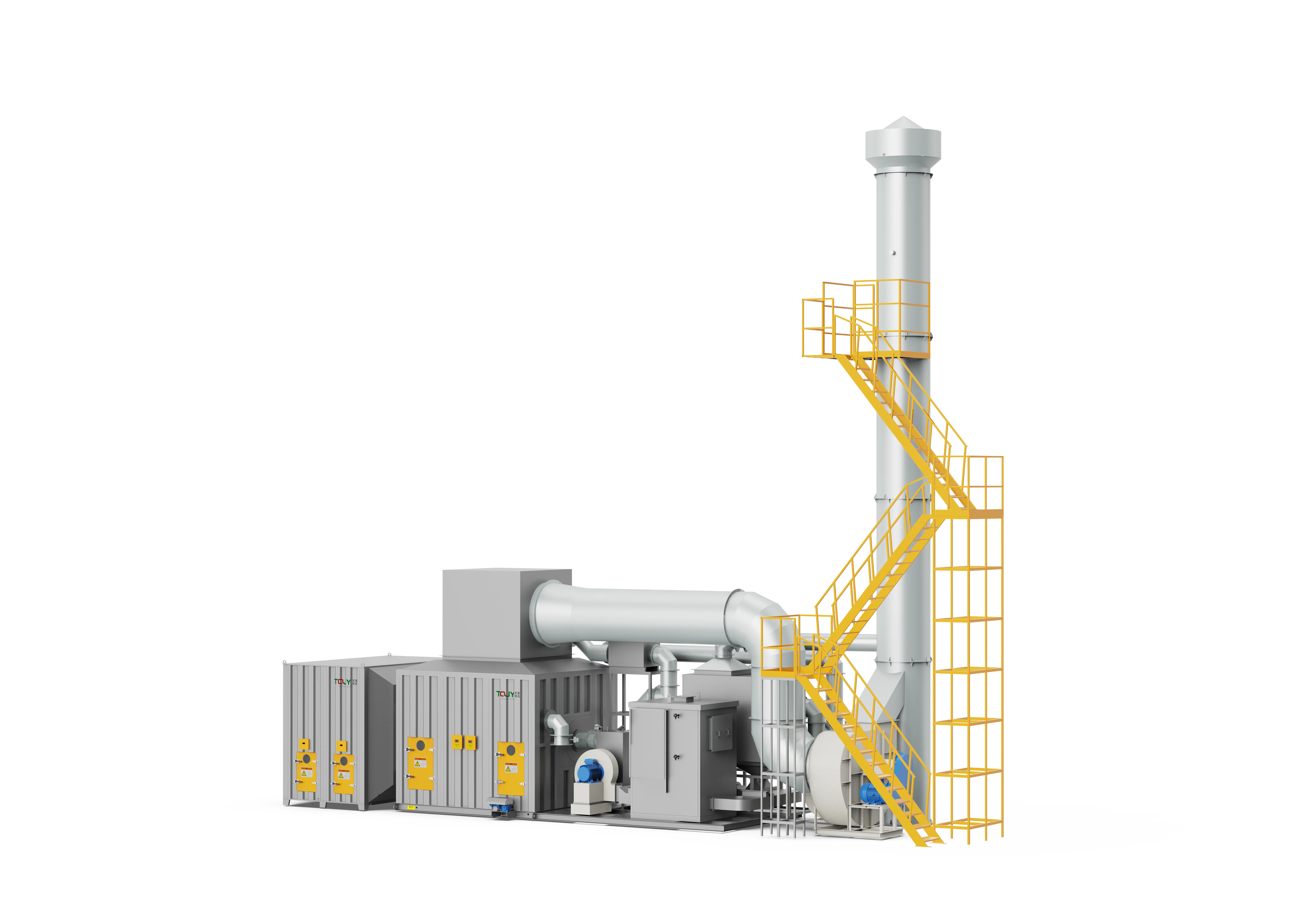
Equipment views
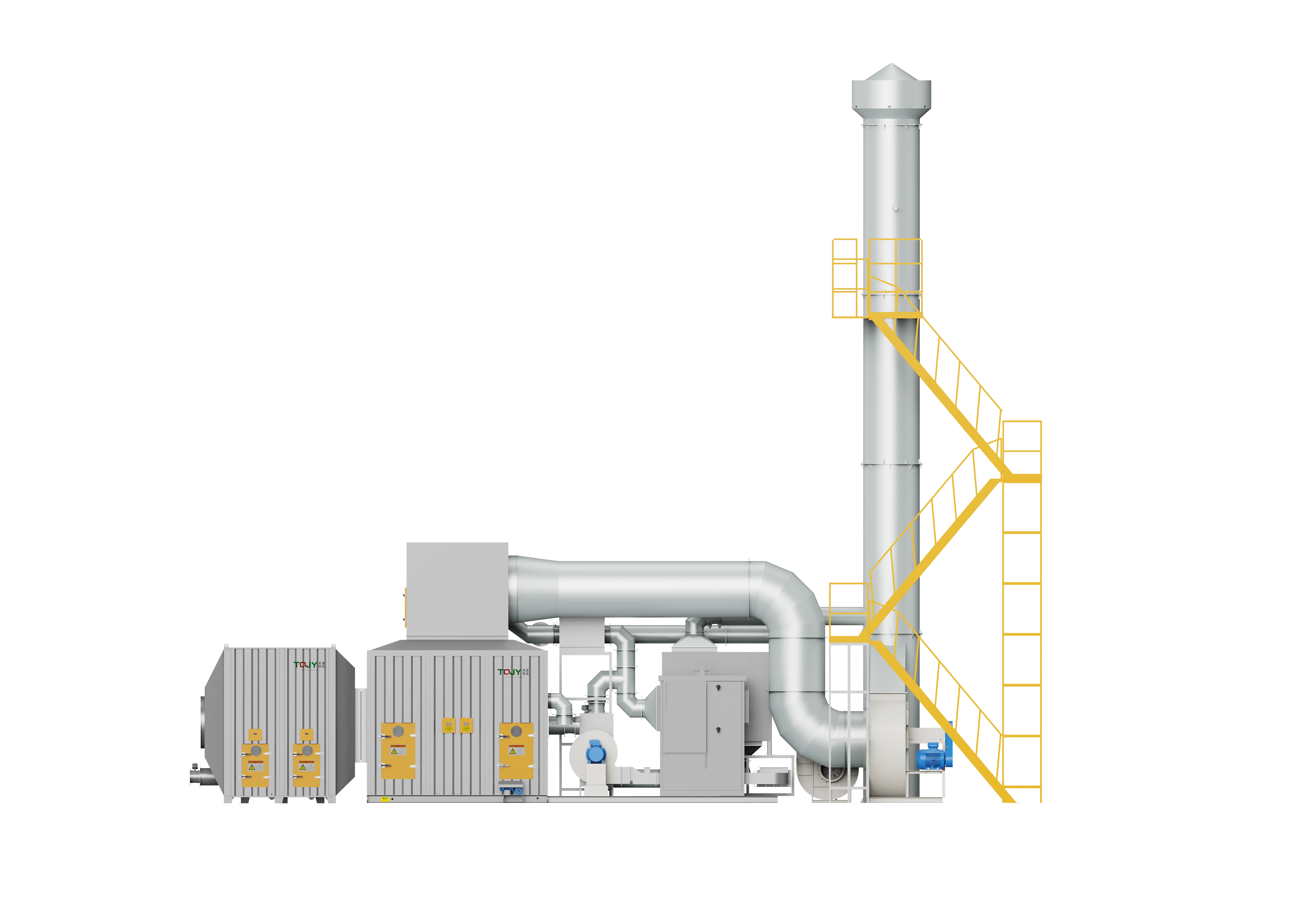
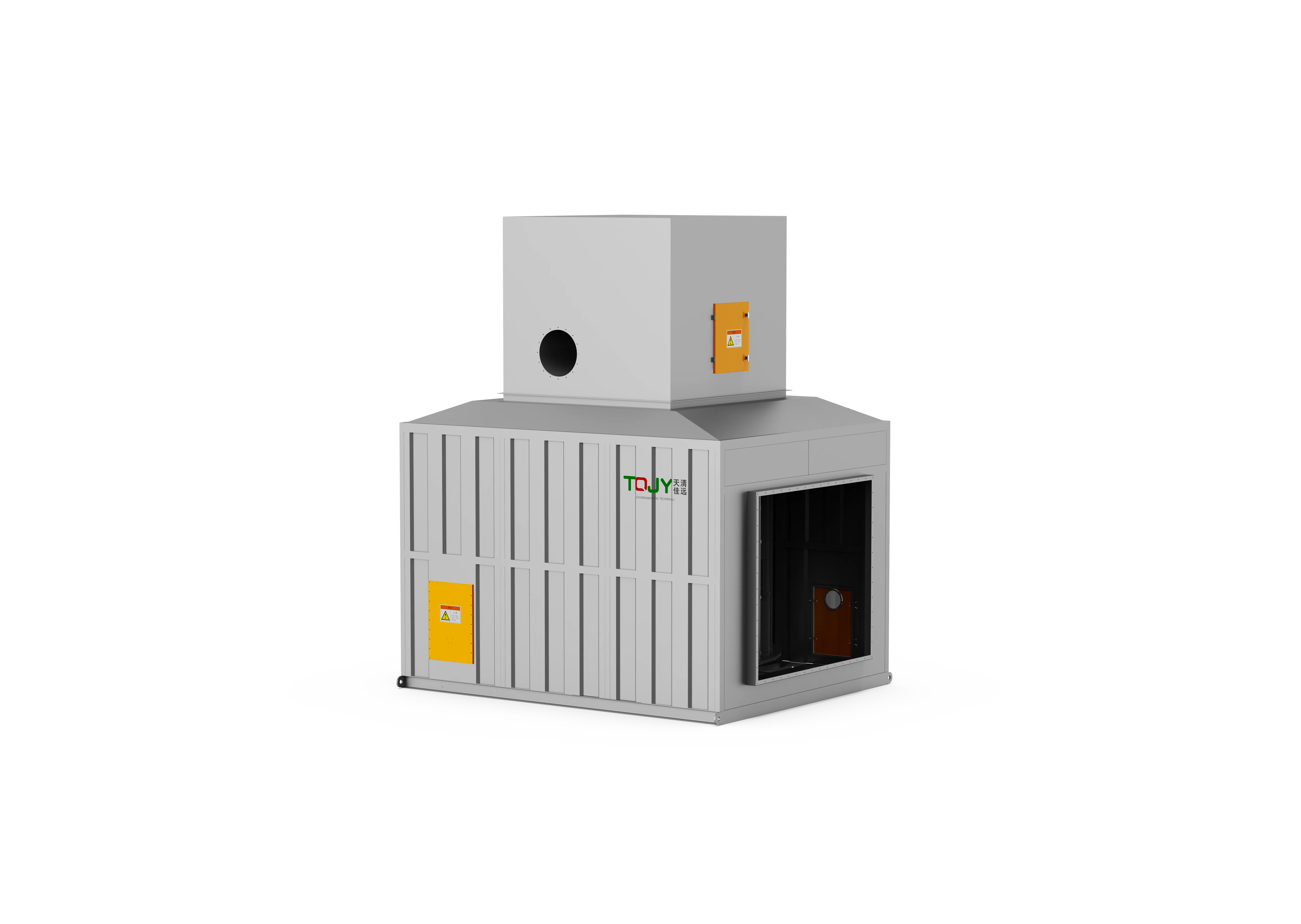
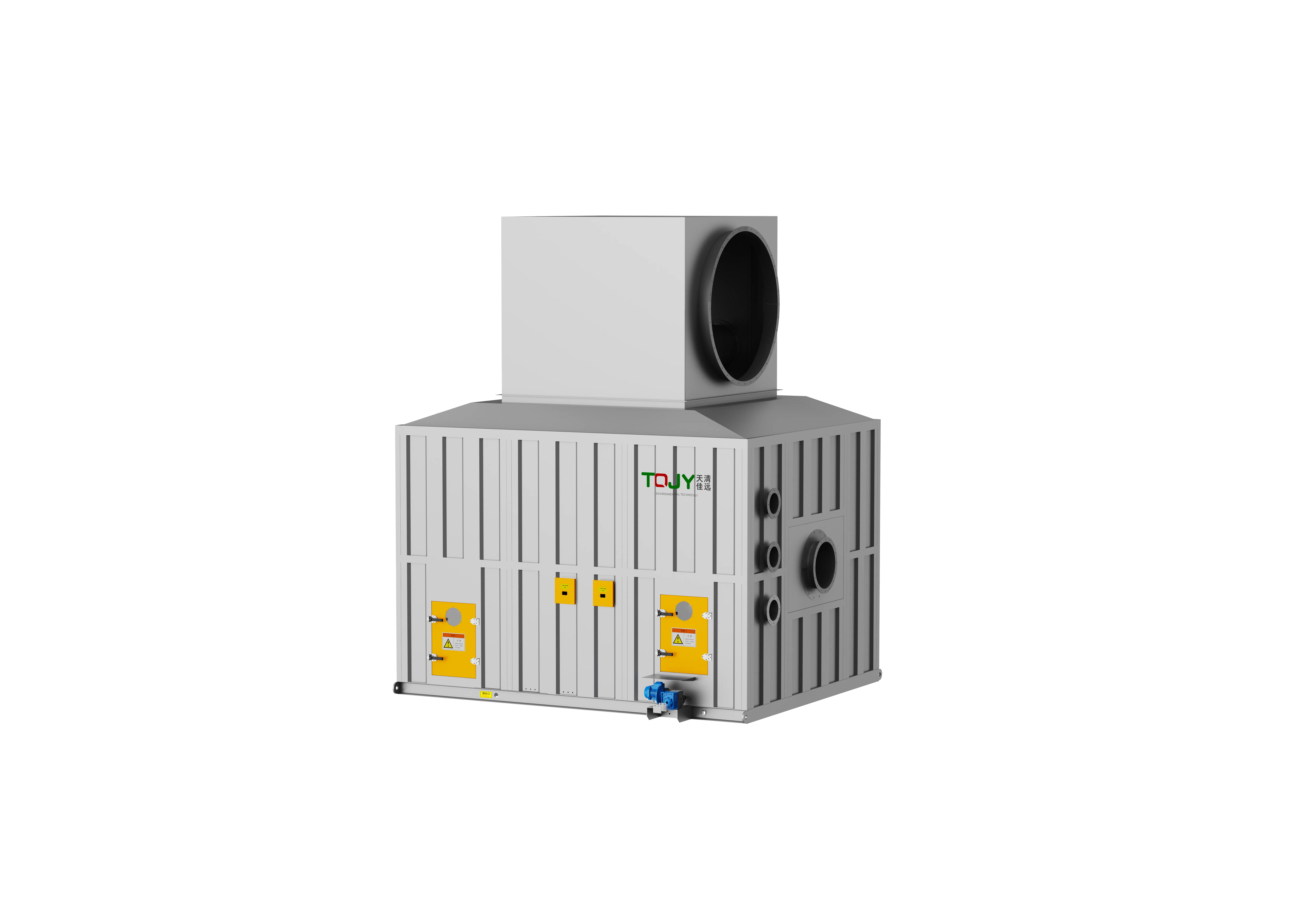
Product images show representative FluxFine configurations. Final dimensions, materials and interfaces follow the approved project design.
Technical Parameters
Detailed parameter models for engineering selection and sizing. Note that dimensions and efficiencies are for reference under nominal conditions.
| Model | Airflow (m³/h) | Inlet VOCs (mg/m³) | Efficiency | Ratio (x) | Dimensions (m) |
|---|---|---|---|---|---|
| Cylindrical Rotor Models | |||||
| TQJY-ZR-T10L | 10000 | 150 | 90% | 10 | 2.8 × 2.3 × 1.3 |
| TQJY-ZR-T10M | 10000 | 350 | 93% | 10 | 2.8 × 2.3 × 1.3 |
| TQJY-ZR-T10H | 10000 | 600 | 95% | 10 | 2.8 × 2.3 × 1.3 |
| TQJY-ZR-T20L | 20000 | 150 | 90% | 20 | 3.2 × 2.6 × 1.6 |
| TQJY-ZR-T20M | 20000 | 350 | 93% | 15 | 3.2 × 2.6 × 1.6 |
| TQJY-ZR-T20H | 20000 | 600 | 95% | 10 | 3.2 × 2.6 × 1.8 |
| TQJY-ZR-T30L | 30000 | 150 | 90% | 20 | 3.2 × 2.6 × 2.0 |
| TQJY-ZR-T30M | 30000 | 350 | 93% | 15 | 3.2 × 2.6 × 2.0 |
| TQJY-ZR-T30H | 30000 | 600 | 95% | 10 | 3.2 × 2.6 × 2.3 |
| TQJY-ZR-T40L | 40000 | 150 | 90% | 20 | 3.2 × 2.6 × 2.3 |
| TQJY-ZR-T40M | 40000 | 350 | 93% | 15 | 3.2 × 2.6 × 2.3 |
| TQJY-ZR-T40H | 40000 | 600 | 95% | 10 | 4.0 × 3.0 × 2.3 |
| TQJY-ZR-T50L | 50000 | 150 | 90% | 20 | 4.0 × 3.0 × 2.3 |
| TQJY-ZR-T50M | 50000 | 350 | 93% | 15 | 4.0 × 3.0 × 2.3 |
| TQJY-ZR-T50H | 50000 | 600 | 95% | 10 | 4.0 × 3.0 × 2.6 |
| TQJY-ZR-T60L | 60000 | 150 | 90% | 20 | 4.0 × 3.0 × 2.6 |
| TQJY-ZR-T60M | 60000 | 350 | 93% | 15 | 4.0 × 3.0 × 2.6 |
| TQJY-ZR-T60H | 60000 | 600 | 95% | 10 | 4.2 × 3.3 × 2.6 |
| TQJY-ZR-T70L | 70000 | 150 | 90% | 20 | 4.2 × 3.3 × 2.6 |
| TQJY-ZR-T70M | 70000 | 350 | 93% | 15 | 4.2 × 3.3 × 2.9 |
| TQJY-ZR-T70H | 70000 | 600 | 95% | 10 | 4.2 × 3.3 × 2.9 |
| TQJY-ZR-T80L | 80000 | 150 | 90% | 20 | 4.2 × 3.3 × 2.6 |
| TQJY-ZR-T80M | 80000 | 350 | 93% | 15 | 4.2 × 3.3 × 2.9 |
| TQJY-ZR-T80H | 80000 | 600 | 95% | 10 | 4.5 × 3.5 × 2.9 |
| TQJY-ZR-T90L | 90000 | 150 | 90% | 20 | 4.5 × 3.5 × 2.9 |
| TQJY-ZR-T90M | 90000 | 350 | 93% | 15 | 4.5 × 3.5 × 2.9 |
| TQJY-ZR-T90H | 90000 | 600 | 95% | 10 | 4.5 × 3.5 × 3.2 |
| TQJY-ZR-T100L | 100000 | 150 | 90% | 20 | 4.5 × 3.5 × 3.2 |
| TQJY-ZR-T100M | 100000 | 350 | 93% | 15 | 4.5 × 3.5 × 3.2 |
| TQJY-ZR-T100H | 100000 | 600 | 95% | 10 | 4.5 × 3.5 × 3.2 |
| TQJY-ZR-T120L | 120000 | 150 | 90% | 20 | 4.5 × 3.5 × 3.6 |
| TQJY-ZR-T120M | 120000 | 350 | 93% | 15 | 4.5 × 3.5 × 3.6 |
| TQJY-ZR-T120H | 120000 | 600 | 95% | 10 | 4.5 × 3.5 × 3.6 |
| TQJY-ZR-T140L | 140000 | 150 | 90% | 20 | 4.5 × 3.5 × 3.6 |
| TQJY-ZR-T140M | 140000 | 350 | 93% | 15 | 4.9 × 3.9 × 3.6 |
| TQJY-ZR-T140H | 140000 | 600 | 95% | 10 | 4.9 × 3.9 × 3.6 |
| TQJY-ZR-T160L | 160000 | 150 | 90% | 20 | 4.9 × 3.9 × 3.6 |
| TQJY-ZR-T160M | 160000 | 350 | 93% | 15 | 4.9 × 3.9 × 3.6 |
| TQJY-ZR-T160H | 160000 | 600 | 95% | 10 | 5.4 × 4.4 × 3.6 |
| TQJY-ZR-T180L | 180000 | 150 | 90% | 20 | 5.4 × 4.4 × 3.6 |
| TQJY-ZR-T180M | 180000 | 350 | 93% | 15 | 5.4 × 4.4 × 3.6 |
| TQJY-ZR-T180H | 180000 | 600 | 95% | 10 | 5.4 × 4.4 × 4.0 |
| TQJY-ZR-T200L | 200000 | 150 | 90% | 20 | 5.4 × 4.4 × 4.0 |
| TQJY-ZR-T200M | 200000 | 350 | 93% | 15 | 5.4 × 4.4 × 4.0 |
| TQJY-ZR-T200H | 200000 | 600 | 95% | 10 | 5.4 × 4.4 × 4.0 |
| TQJY-ZR-T220L | 220000 | 150 | 90% | 20 | 5.4 × 4.4 × 4.0 |
| TQJY-ZR-T220M | 220000 | 350 | 93% | 15 | 5.4 × 4.4 × 4.0 |
| TQJY-ZR-T220H | 220000 | 600 | 95% | 10 | 5.6 × 4.6 × 4.0 |
| Disc Rotor Models | |||||
| TQJY-ZR-P10M | 10000 | 500 | 95% | 12 | 2.1 × 1.55 × 1.65 |
| TQJY-ZR-P10H | 10000 | 1000 | 97% | 8 | 2.1 × 1.85 × 1.95 |
| TQJY-ZR-P20M | 20000 | 500 | 95% | 12 | 2.1 × 2.05 × 2.15 |
| TQJY-ZR-P20H | 20000 | 1000 | 97% | 8 | 2.1 × 2.55 × 2.65 |
| TQJY-ZR-P30M | 30000 | 500 | 95% | 12 | 2.1 × 2.55 × 2.65 |
| TQJY-ZR-P30H | 30000 | 1000 | 97% | 8 | 2.1 × 2.8 × 2.9 |
| TQJY-ZR-P40M | 40000 | 500 | 95% | 12 | 2.1 × 3.0 × 3.1 |
| TQJY-ZR-P40H | 40000 | 1000 | 97% | 8 | 2.1 × 3.0 × 3.1 |
| TQJY-ZR-P50M | 50000 | 500 | 95% | 12 | 2.1 × 3.3 × 3.4 |
| TQJY-ZR-P50H | 50000 | 1000 | 97% | 8 | 2.1 × 3.3 × 3.4 |
| TQJY-ZR-P60M | 60000 | 500 | 95% | 12 | 2.1 × 3.6 × 3.8 |
| TQJY-ZR-P60H | 60000 | 1000 | 97% | 8 | 2.1 × 3.6 × 3.8 |
| TQJY-ZR-P70M | 70000 | 500 | 95% | 12 | 2.1 × 3.9 × 4.1 |
| TQJY-ZR-P70H | 70000 | 1000 | 97% | 8 | 2.1 × 3.9 × 4.1 |
| TQJY-ZR-P80M | 80000 | 500 | 95% | 12 | 2.1 × 4.2 × 4.4 |
| TQJY-ZR-P80H | 80000 | 1000 | 97% | 8 | 2.1 × 4.2 × 4.4 |
| TQJY-ZR-P90M | 90000 | 500 | 95% | 12 | 2.1 × 4.4 × 4.6 |
| TQJY-ZR-P90H | 90000 | 1000 | 97% | 8 | 2.1 × 4.4 × 4.6 |
| TQJY-ZR-P100M | 100000 | 500 | 95% | 12 | 2.1 × 4.7 × 4.9 |
| TQJY-ZR-P100H | 100000 | 1000 | 97% | 8 | 2.1 × 4.7 × 4.9 |
| TQJY-ZR-P120M | 120000 | 500 | 95% | 12 | 2.1 × 5.0 × 5.2 |
| TQJY-ZR-P120H | 120000 | 1000 | 97% | 8 | 2.1 × 5.0 × 5.2 |
| TQJY-ZR-P140M | 140000 | 500 | 95% | 12 | 2.1 × 5.3 × 5.5 |
| TQJY-ZR-P140H | 140000 | 1000 | 97% | 8 | 2.1 × 5.3 × 5.5 |
Proven Zeolite Rotor installations
Review documented treatment trains featuring Zeolite Rotor technology across various industrial processes.
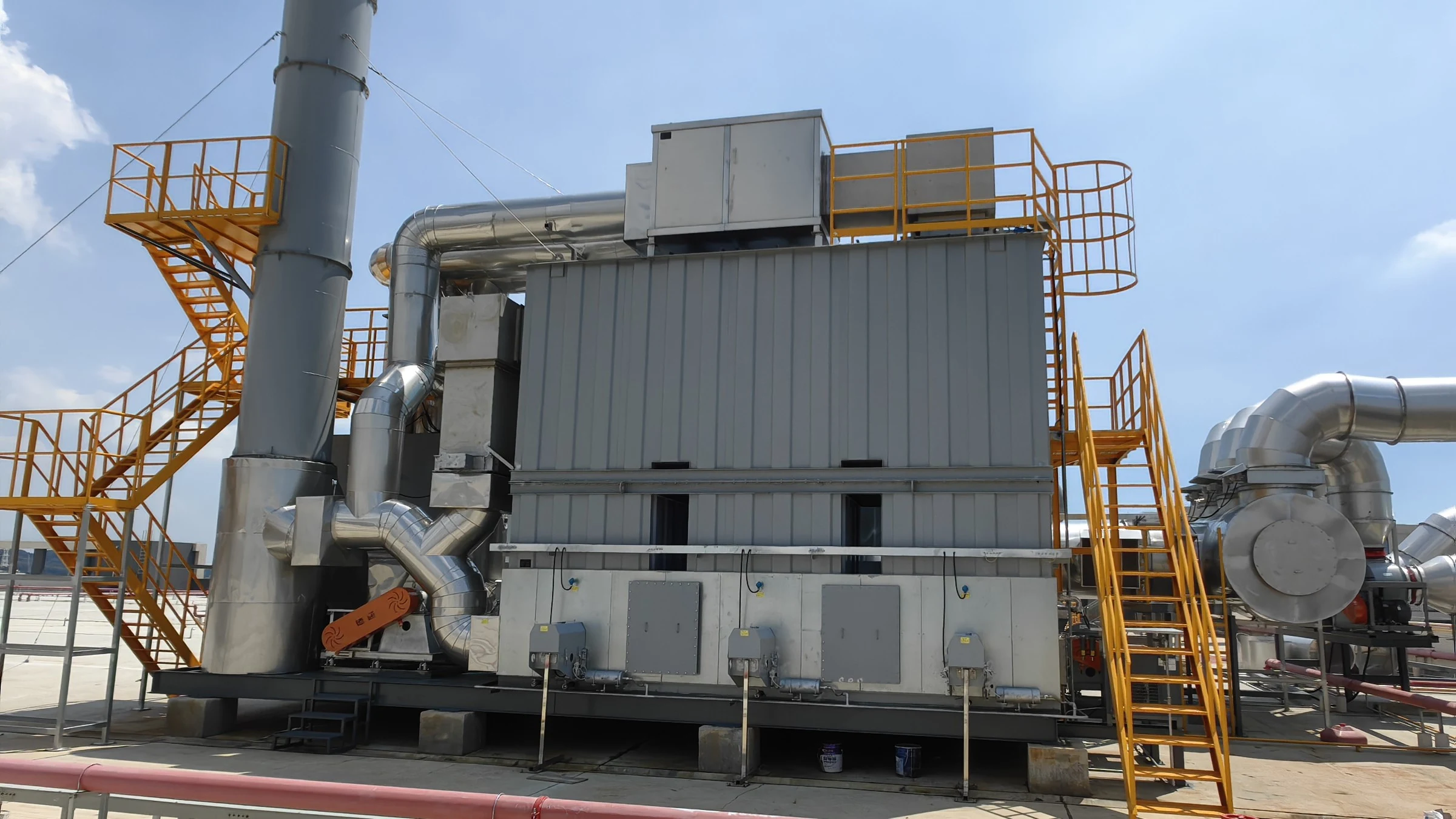
450,000 m³/h (265,000 CFM) · Architectural aluminum profile automated fluorocarbon (PVDF) spray coating and curing lines
450,000 m³/h Dual Zeolite Rotor & 3-Bed RTO System for JMA Aluminum Fluorocarbon Coating Lines
Dual-Train Zeolite Rotor (2×220k m³/h) + 3-Bed RTO (55k m³/h) + Dual Jet Scrubbers + 4-Stage Dry Filtration
Read project reference →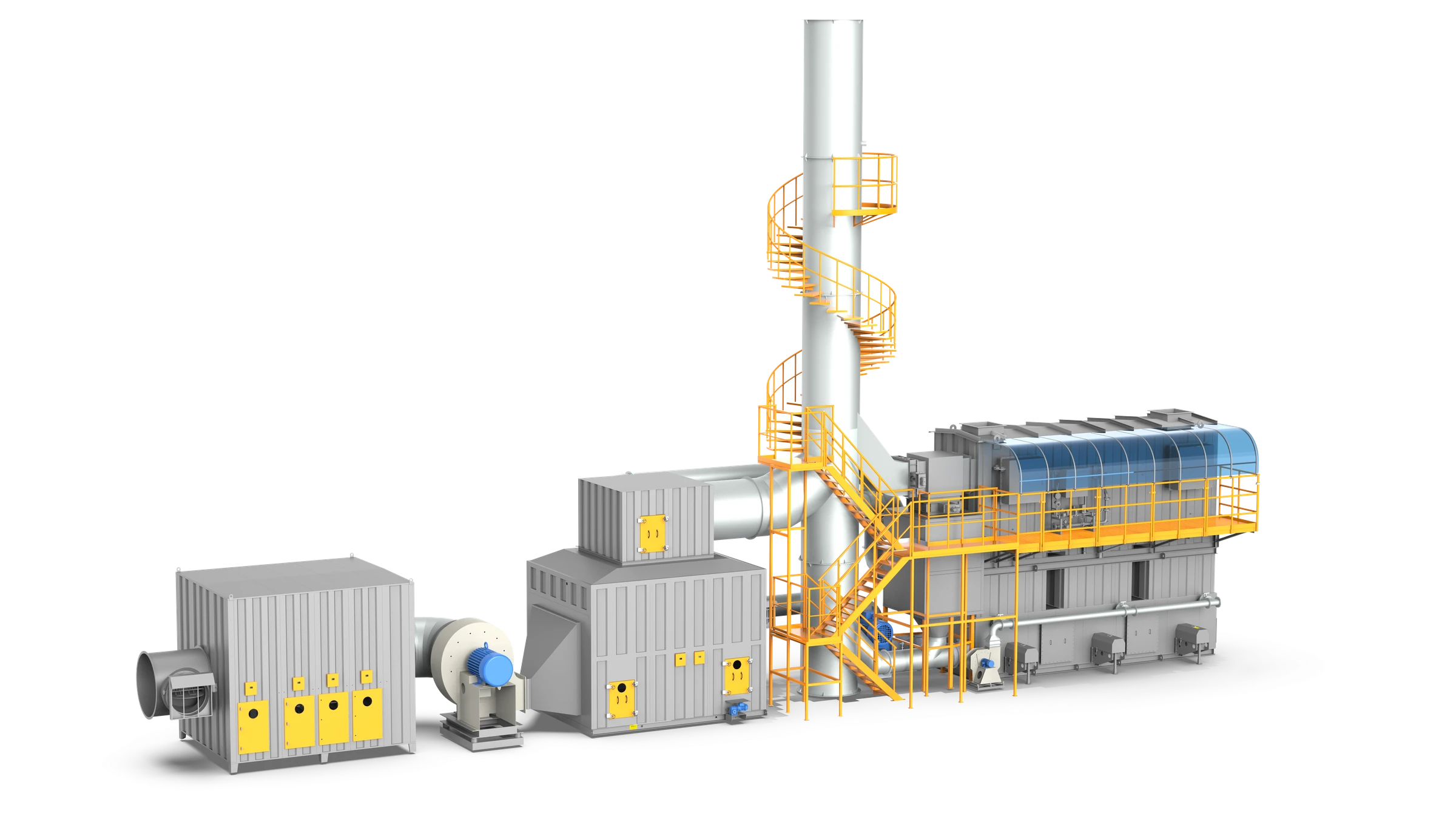
200,000 m³/h (117,600 CFM) · Commercial vehicle & tanker spray coating and curing
200,000 m³/h Zeolite Drum & 3-Bed RTO System for CIMC Vehicles
5-Stage HEPA Dry Filtration (G4-H11) + Cylindrical Zeolite Drum Concentrator + 3-Bed RTO
Read project reference →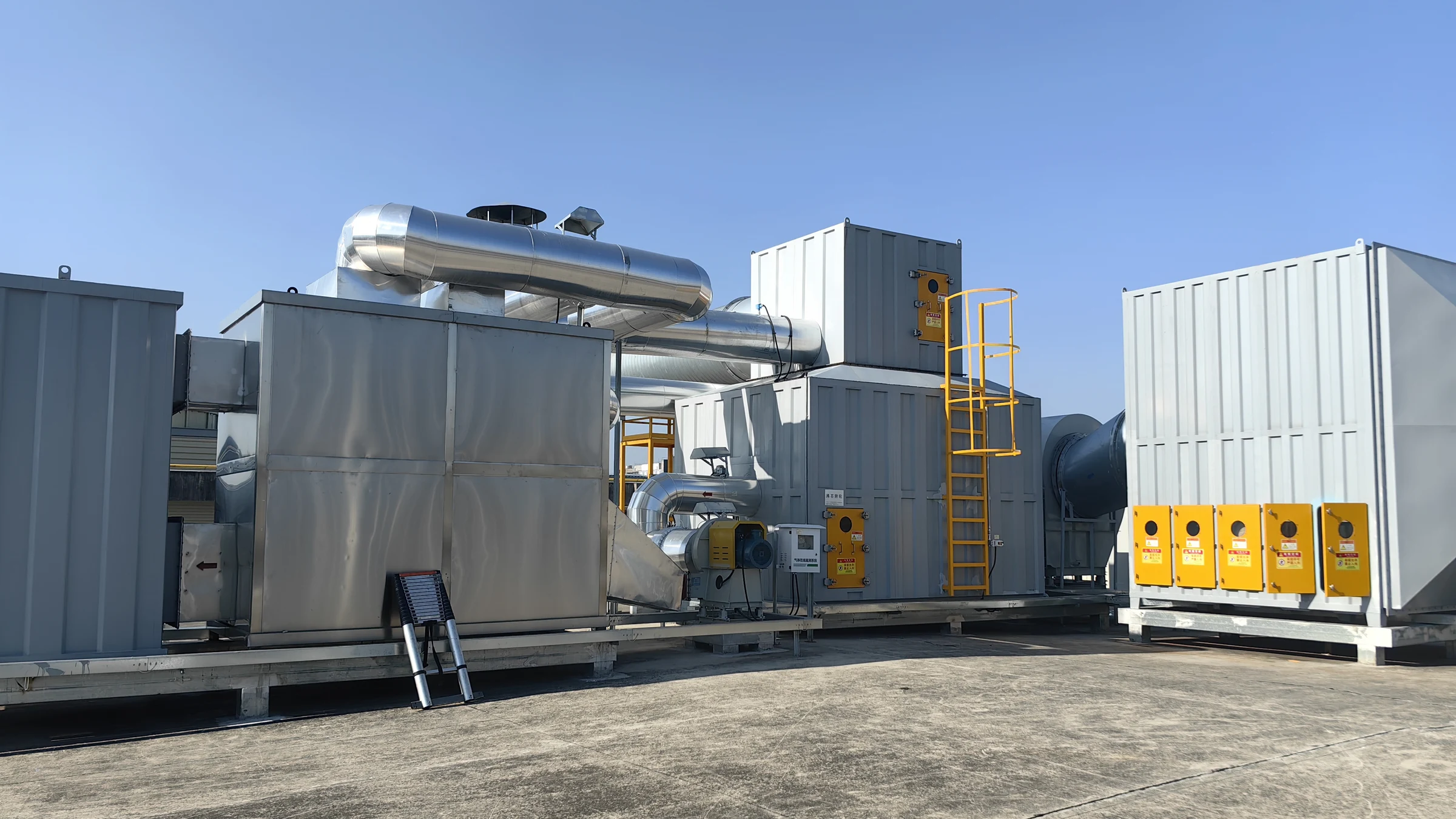
170,000 m³/h (100,000 CFM) · Glass spray-painting and silk-screening
170,000 m³/h VOC Abatement System for Glass Spray-Painting and Silk-Screening
Multi-Stage Dry Filtration (G4-F9) + Cylinder Zeolite Rotor + Catalytic Oxidizer (CO)
Read project reference →Configure Zeolite Rotor for your plant
Share measured process data so the engineering team can confirm suitability, pretreatment, equipment size and scope boundaries.
Source basis: Published values are selection references, not a project guarantee.