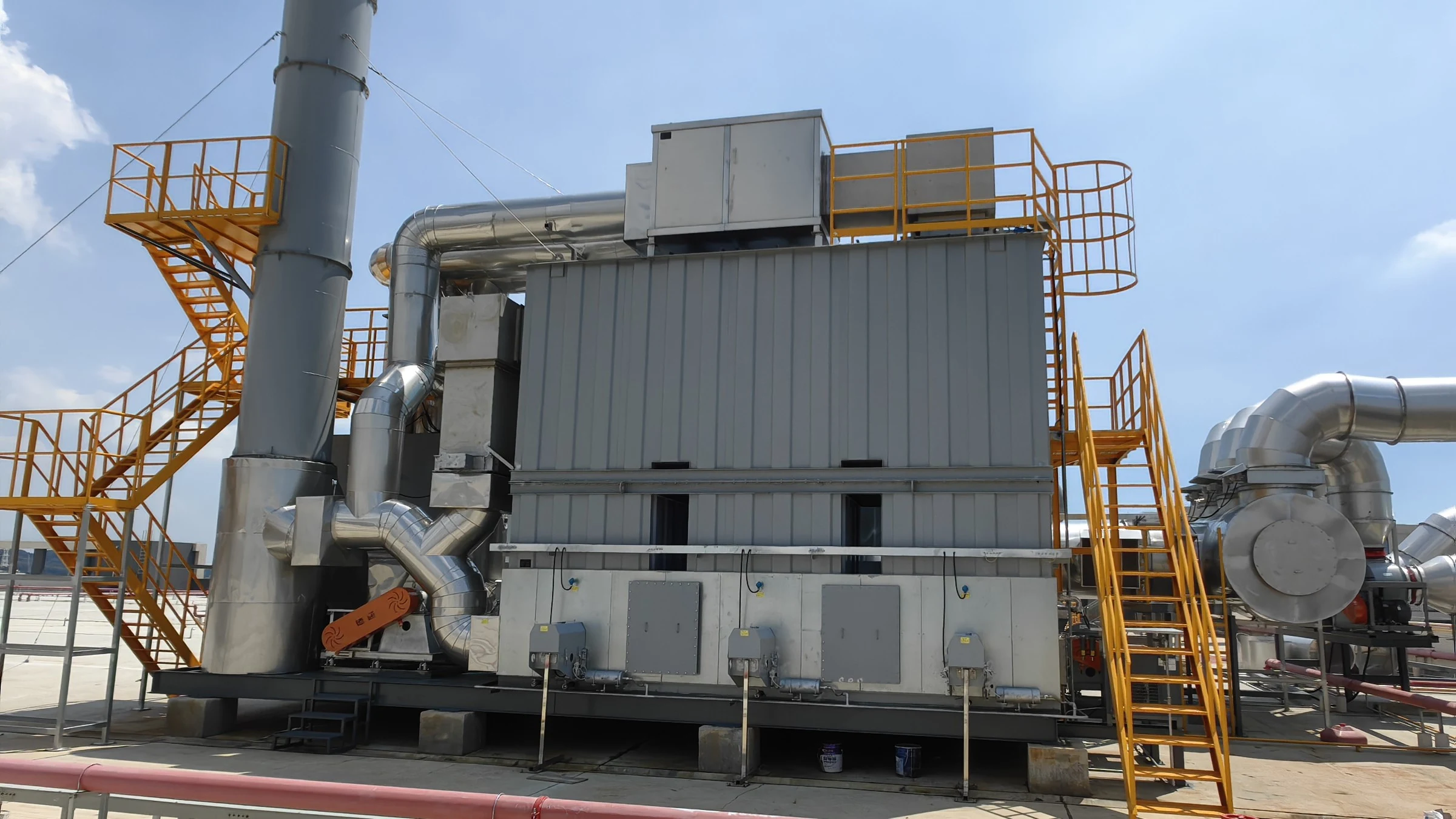
450,000 m³/h Dual Zeolite Rotor & 3-Bed RTO Abatement System
Guangdong JMA Aluminum Profile Factory (Group) Co., Ltd. | Automated Fluorocarbon Coating Lines
Colossal 450,000 m³/h Fluorocarbon Coating Streams — Mastered by Dual Zeolite Rotors & 3-Bed RTO
Guangdong JMA Aluminum Profile Factory (Group) Co., Ltd. (坚美铝业) is a globally celebrated pioneer in high-performance aluminum extrusions, curtain wall structural systems, and precision industrial alloys. As an authoritative supplier to world-renowned architectural icons — including the Burj Khalifa in Dubai, the Canton Tower in Guangzhou, and the Ping An Finance Centre in Shenzhen — JMA enforces stringent quality and environmental standards across all manufacturing phases.
At JMA’s Nanhai manufacturing campus in Foshan, two continuous automated fluorocarbon (PVDF) profile spray coating lines operate under heavy production schedules. The multi-stage finishing operations — comprising automated primer, basecoat, topcoat, and clearcoat booths, flash-off leveling chambers, and continuous thermal curing ovens — generate an immense collective exhaust stream of 450,000 m³/h (265,000 CFM). The stream carries volatile organic compounds (butyl cellosolve, butyl carbitol, MEK, xylene, and toluene) alongside aerosolized polymeric paint mist droplets.
FluxFine engineered and commissioned a turnkey mega-scale abatement installation: a Dual-Train 220,000 m³/h Zeolite Rotor Concentrator paired with a Central 55,000 m³/h Three-Bed Regenerative Thermal Oxidizer (3-Bed RTO). Integrated with dual-stage jet-mixing scrubbers, four-stage differential-pressure-monitored dry filters, and a direct curing oven thermal injection header, the installation delivers verified ≥99.2% overall VOC Destruction and Removal Efficiency (DRE), suppresses stack emissions to NMHC ≤ 20 mg/m³, and sustains continuous 100% autothermal operation with zero auxiliary fuel consumption during regular production.
Quantified Engineering & Operational Benchmarks
Engineered for round-the-clock heavy industrial duty, the centralized multi-train architecture delivers verified environmental compliance, zero auxiliary fuel dependence, and multi-year media protection.
Three-bed alternating configuration with clean-gas purge chamber completely suppresses transient valve-switching slip, delivering verified ≥99.2% destruction.
Outperforms the Guangdong DB44/2367-2022 ceiling (60 mg/m³) by 66%, easily meeting the European Union BAT industrial emissions benchmark.
At desorbed VOC concentrations ≥1.8 g/m³, oxidation enthalpy sustains 800°C combustion with zero supplemental burner gas required.
Dual-stage jet kinetic scrubbers plus 4-stage dry filtration arrest polymeric overspray down to PM ≤ 1 mg/m³, safeguarding zeolite molecular pores.
Four Severe Engineering Hurdles Overcome
Automated architectural profile coating imposes complex fluid dynamics, sticky polymeric aerosols, and extreme volumetric swings that defeat ordinary off-the-shelf air scrubbers.
Massive Dilute Airflow Volume
The dual fluorocarbon spray lines require 400,000 m³/h (235,000 CFM) of clean sweep ventilation to satisfy GB 14444-2006 cross-sectional air speeds (0.30 m/s). Direct thermal incineration of such a gigantic, dilute stream (~450–500 mg/m³) would demand prohibitive fuel expenditures.
Sticky Polymeric PVDF Overspray
Fluorocarbon paint droplets form exceptionally tenacious, hydrophobic adhesive films when drying. If raw paint mist reaches zeolite rotors, microscopic channels blind permanently within weeks, destroying adsorption capacity and causing irreversible media damage.
High-Boiling Glycol Ether Solvents
PVDF coatings rely heavily on butyl carbitol (boiling point 230.4°C) and butyl cellosolve (168.4°C). Ordinary carbon adsorbers fail to desorb these heavy polar ethers, causing bed poisoning and fire risks. High-temperature zeolite desorption (≥180°C–220°C) is essential.
Single-Line vs Dual-Line Flexibility
Production schedules alternate dynamically between full double-line operation, single-line production, or weekend maintenance. The abatement system required independent modular trains to eliminate massive fan idling losses during partial plant operation.
Process Train & Stream Balancing Flowchart
A dual-train pre-conditioned adsorption-desorption train linked to a central high-efficiency 3-Bed RTO, with direct thermal integration of curing oven flue gas.
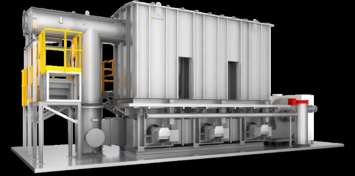
Central 55,000 m³/h (32,400 CFM) Three-Bed RTO (3-Bed RTO)
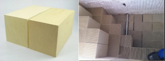
Combines 35,000 m³/h rich desorption air + 20,000 m³/h curing oven exhaust. LANTEC structured ceramic media delivers ≥95% thermal recovery, operating in self-sustaining 100% autothermal balance at 760°C–820°C.
Technical Excellence in Heavy Profile Surface Treatment
How FluxFine solved the high-volume dilemma through multi-barrier particle defense, high-temperature zeolite desorption, and direct oven enthalpy integration.
Four-Tier Particulate Defense Shields Zeolite Rotor Media
In architectural aluminum finishing, overspray droplets that bypass water curtains polymerize into impervious gummy films. If even minor traces reach the adsorption channels of the zeolite rotor, the microscopic lattice becomes irreversibly blinded.
FluxFine implemented a dual-stage jet-mixing scrubber followed by a 4-tier dry filtration box: G4 coarse → F7 bag → F9 dense pleat → coalescing final barrier. Continuous differential pressure sensors monitor each filter tier. The process fans are engineered to maintain rated 220,000 m³/h flow across an extensive resistance band — from clean initial resistance of 350 Pa (1.4 in. w.g.) up to the terminal changeout setpoint of 1,000 Pa (4.0 in. w.g.). This guarantees paint mist entry is strictly suppressed to ≤1 mg/m³.
High-Temperature Desorption of Complex Fluorocarbon Glycols
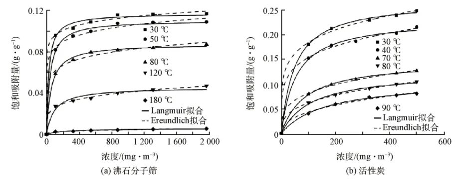
Unlike standard decorative coatings, PVDF fluorocarbon coatings contain high-boiling solvents like diethylene glycol monobutyl ether (butyl carbitol, boiling point 230.4°C) and ethylene glycol monobutyl ether (butyl cellosolve, 168.4°C).
FluxFine’s hydrophobic zeolite molecular sieve rotors tolerate sustained thermal regeneration at 180°C to 220°C without structural degradation. In contrast to granular activated carbon which risks spontaneous ignition and pore fouling from heavy ethers, the inorganic zeolite matrix completely releases polar glycols during each rotation cycle, maintaining a constant 10:1 to 15:1 concentration ratio year-round.
Synergistic Curing Oven Flue Gas Direct Enthalpy Injection
Continuous thermal baking ovens release 20,000 m³/h (11,800 CFM) of exhaust at 60°C to 120°C. Routing this stream through the zeolite rotor would heat the adsorption bed, significantly reducing adsorption efficiency and causing premature desorption leakage.
FluxFine engineered a dedicated thermal bypass header: the curing oven stream passes through stainless steel demisters to eliminate residual aerosol grease, then injects directly into the 3-Bed RTO suction manifold alongside the 35,000 m³/h rich desorption stream. This supplies clean thermal energy directly into the combustion chamber, establishing a self-sustaining autothermal state at lower solvent concentrations.
Three-Tier PLC Automation & Fail-Safe Interlock Matrix
Certified combustion safety and multi-point combustible gas protection governed by a central Siemens S7 PLC architecture.
Continuous Online Diagnostics
- Multi-point optical LEL detectors at booth headers and rotor inlets.
- Upper/lower ceramic bed differential pressure transmitters.
- Redundant dual-thermocouple combustion chamber temperature monitoring.
- UV flame scanners monitoring burner ignition stability.
Siemens S7 PLC & 14" HMI
- Automated single-line / dual-line load tracking and fan VFD modulation.
- Precision poppet valve cycling with 1.0s switching speed and position feedback.
- Pre-ignition 3-minute mechanical purge sequence clearing combustible pockets.
- Historical trend logging and centralized DCS industrial Ethernet uplink.
Instantaneous Emergency Response
- High-limit 25% LEL alarm automatically triggers fresh-air dilution dampers.
- Fast-acting 3-way pneumatic bypass opens in <1.5s via accumulator on power loss.
- Certified rupture discs on combustion chamber relieving overpressure safely.
- Integrated nitrogen fire suppression flange ready for emergency inerting.
Quantified System Parameters & Operating Envelope
Comprehensive engineering design inputs, equipment metallurgy, and guaranteed environmental benchmarks.
| Design Parameter | Engineering Metric Value | US Imperial Equivalent | Standard / Technical Basis |
|---|---|---|---|
| Total System Airflow | 450,000 m³/h | 265,000 CFM | 2 × 220k spray lines + 10k rooms |
| Single Coating Line Flow | 220,000 m³/h | 129,500 CFM | GB 14444-2006 (0.30 m/s face velocity) |
| Curing Oven Flue Stream | 20,000 m³/h | 11,800 CFM | 60°C – 120°C direct to RTO |
| Inlet VOC Concentration | 450 – 500 mg/m³ | ~120 – 135 ppm | Measured PVDF solvent composite |
| Zeolite Concentration Ratio | 10 : 1 – 15 : 1 | 10 : 1 – 15 : 1 | Concentrates 430k to ~35,000 m³/h |
| RTO Processing Volume | 55,000 m³/h | 32,400 CFM | 35k desorption + 20k curing flue |
| Dry Filter Differential Pressure | 350 Pa (Init) / 1,000 Pa (Final) | 1.4 – 4.0 in. w.g. | 4-Stage G4+F7+F9+Coalescer |
| RTO Combustion Temperature | 760°C – 820°C | 1,400°F – 1,508°F | Residence time ≥ 1.0 s |
| Thermal Energy Recovery (TER) | ≥ 95.0% | ≥ 95.0% | LANTEC Structured Ceramic Media |
| Autothermal Balance Threshold | ≥ 1.8 g/m³ in RTO | ≥ 0.78 gr/dscf | Zero auxiliary gas consumption |
| Destruction Efficiency (DRE) | ≥ 99.2% | ≥ 99.2% | Three-bed alternating purge cycle |
| Guaranteed Stack NMHC | ≤ 20 mg/m³ | < 5.5 ppm | Guangdong DB44/2367-2022 / EU BAT |
| Particulate Stack Emission | ≤ 5 mg/m³ | ≤ 0.002 gr/dscf | GB 16297-1996 standard |
Equipment in This Project
Explore the standardized FluxFine industrial air pollution control hardware deployed in the JMA Aluminum installation.
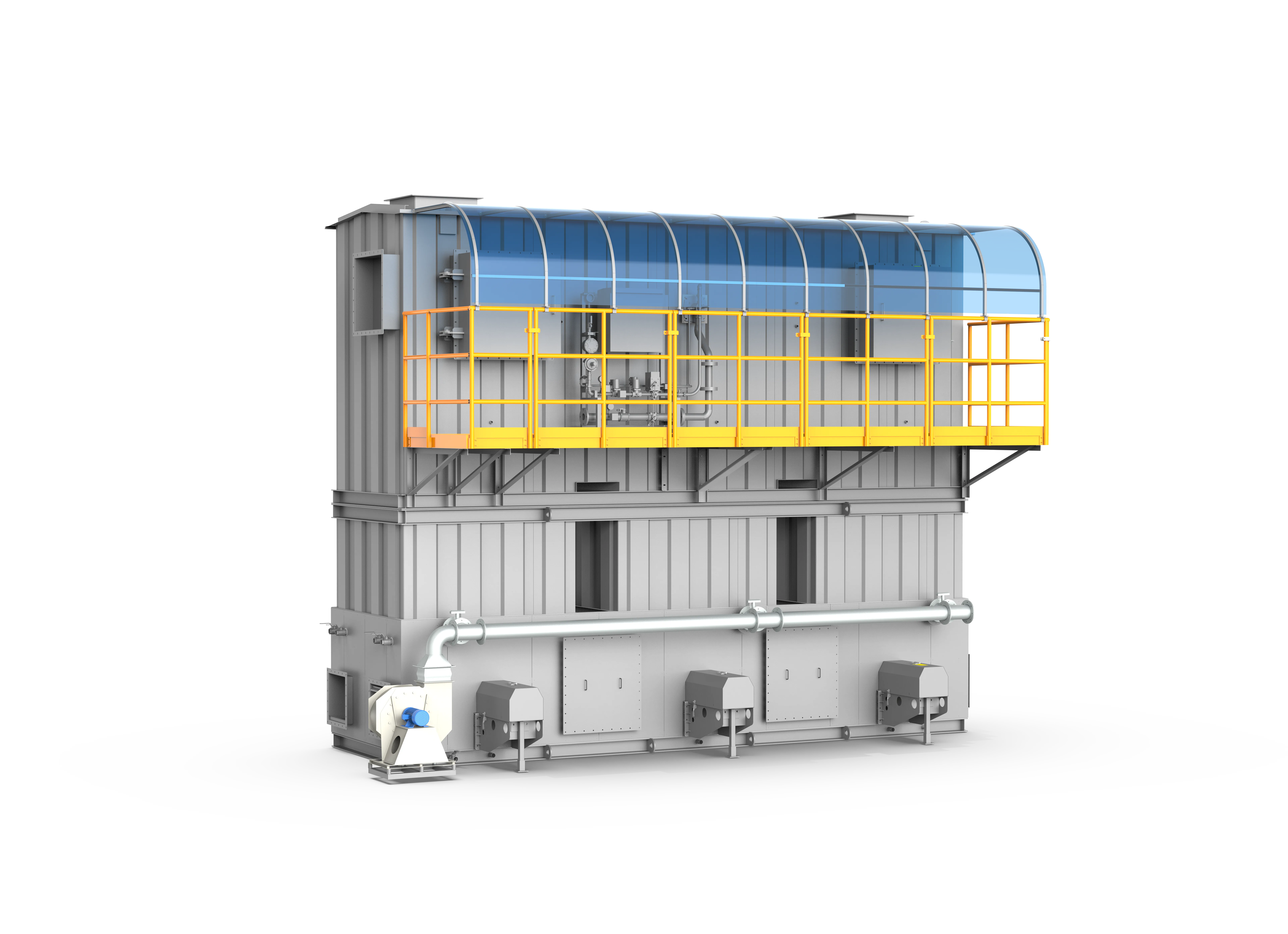
Three-Tower RTO
A premier-grade industrial VOC thermal abatement system that achieves >=99% VOC destruction efficiency and >=95% thermal energy recovery through a classic three-bed alternating heat-exchange and purge process.
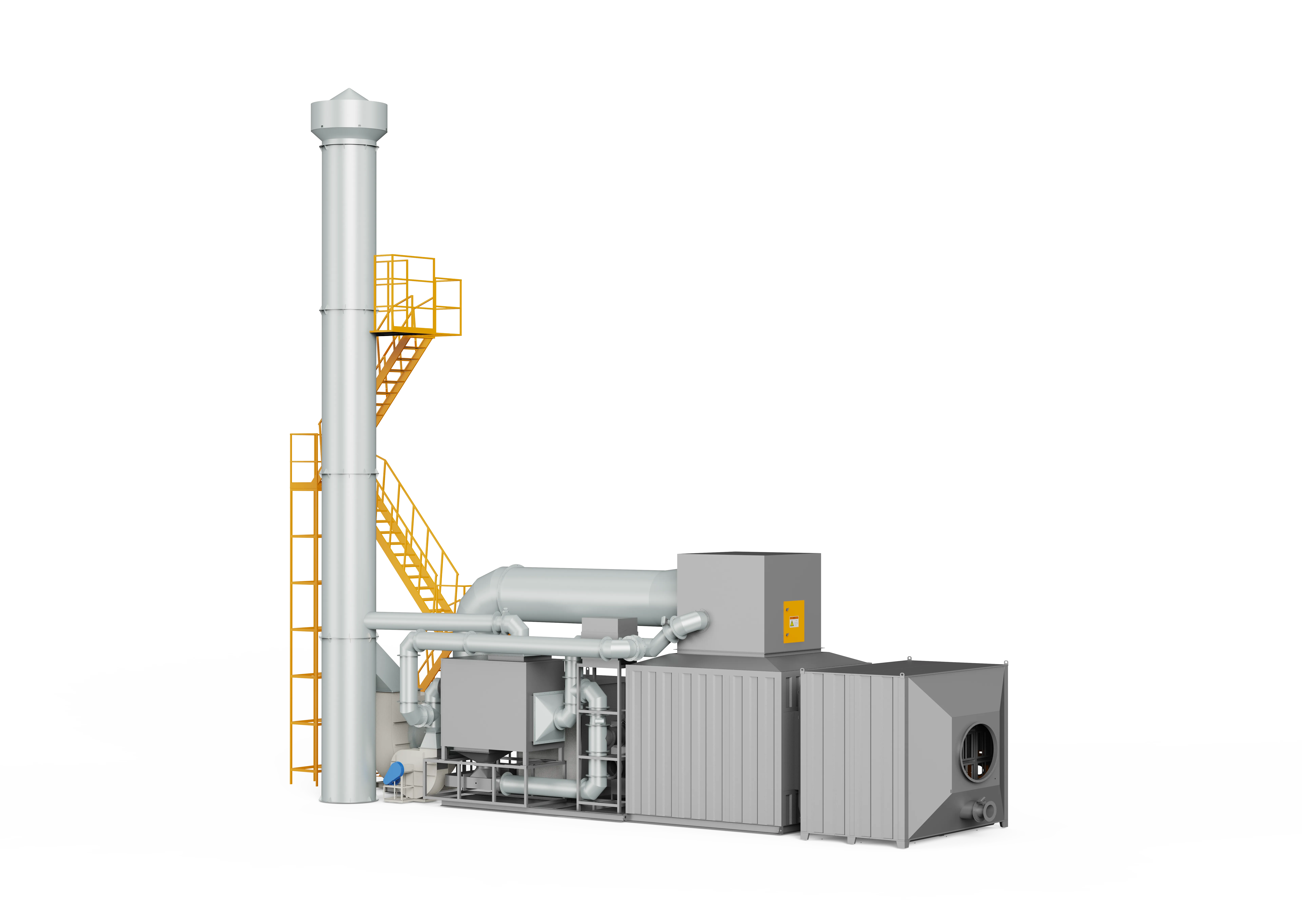
Zeolite Rotor
A high-efficiency VOC pre-treatment and concentration system utilizing advanced hydrophobic zeolite molecular sieves to continuously adsorb, desorb, and enrich large-airflow, low-concentration organic exhaust gases, reducing downstream thermal destruction energy consumption by 40% to over 50%.
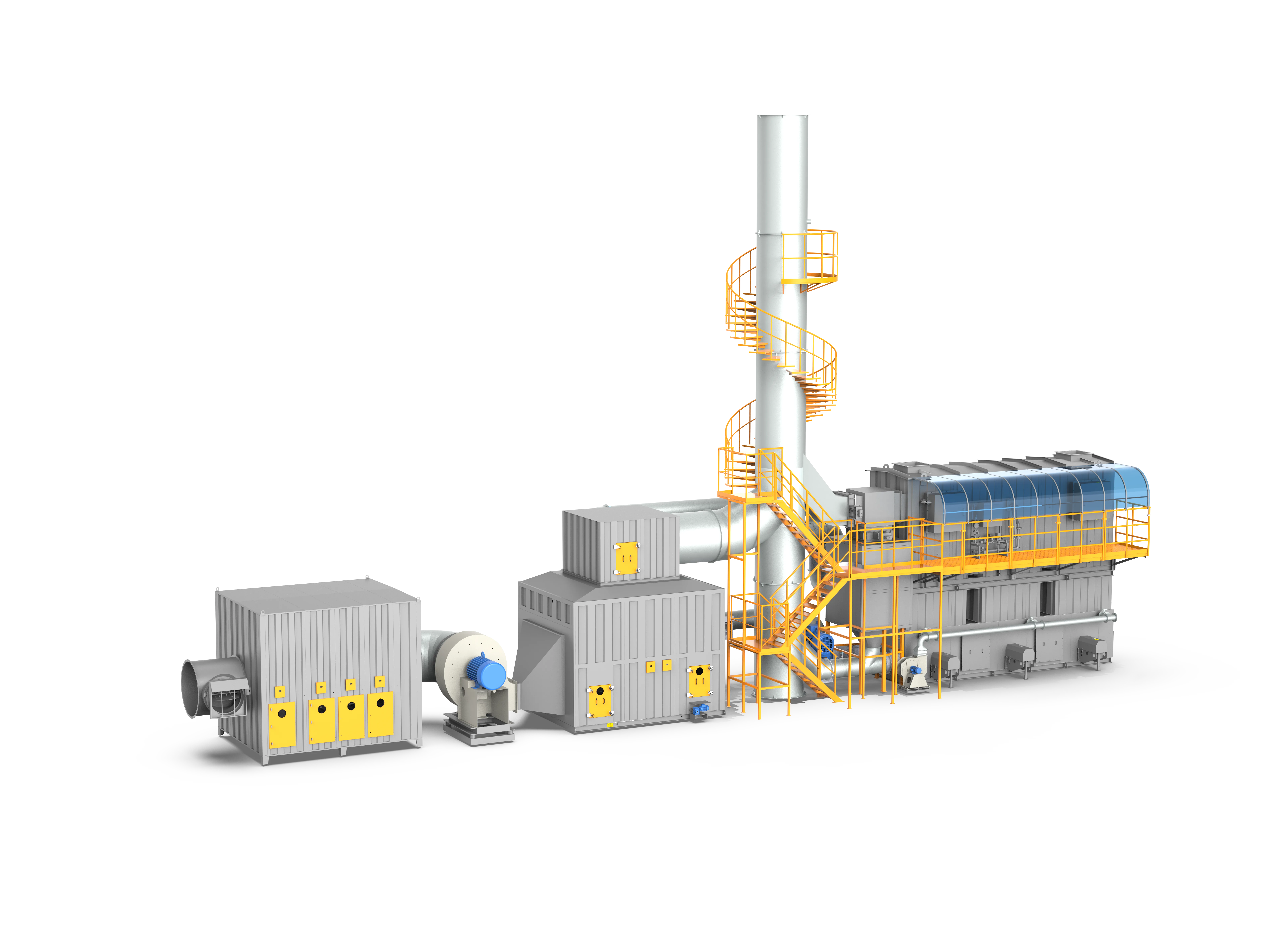
Rotor + 3-Tower RTO
The premier system for large-airflow, low-concentration VOC emissions, combining a hydrophobic zeolite rotor for 10-40x gas enrichment with a mature three-tower RTO for complete destructive oxidation, cutting energy costs by 40%-60%.
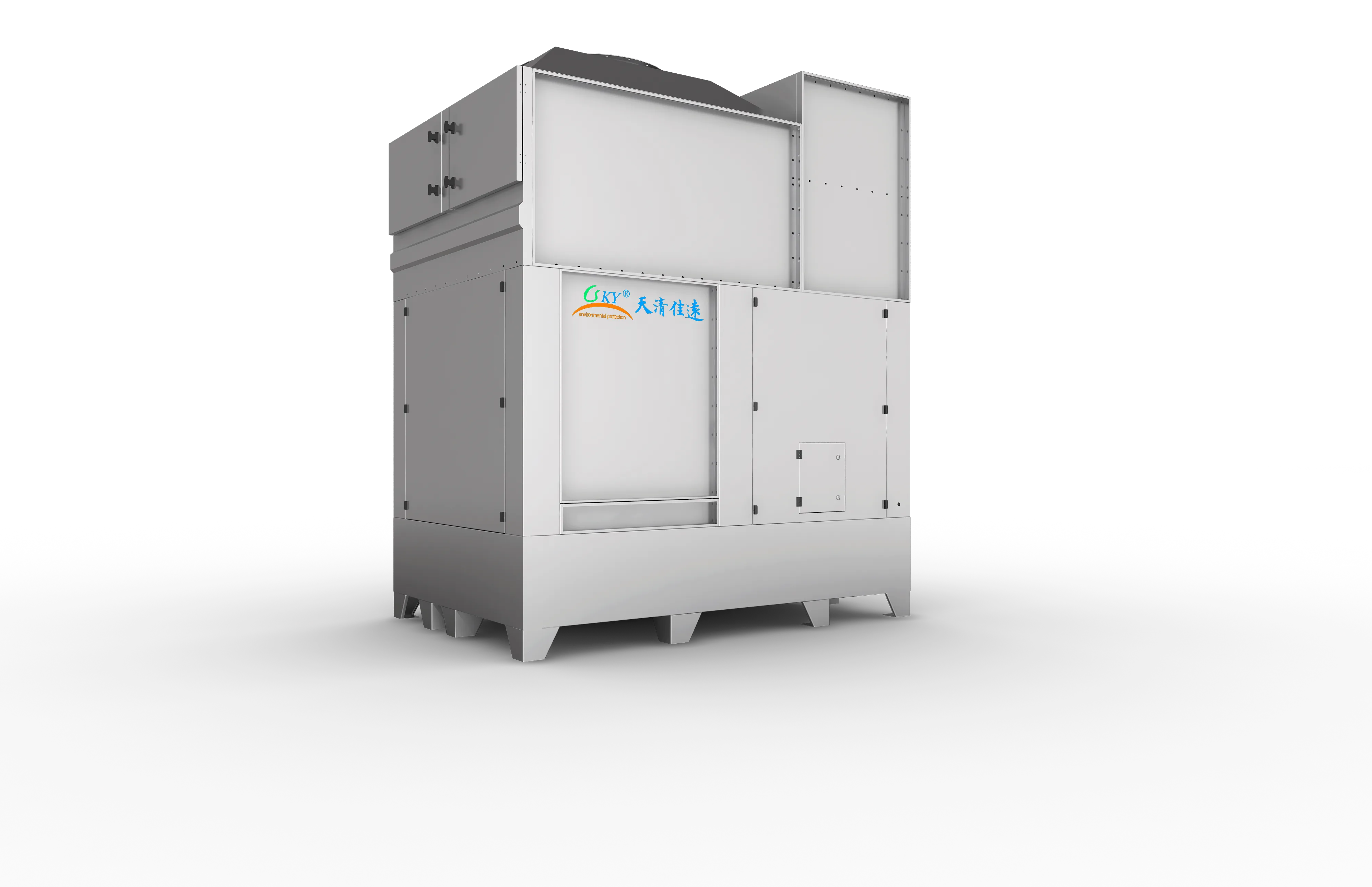
Jet Scrubber
A next-generation wet scrubber utilizing jet-ejection fluid dynamics to self-inhale process gases and generate intensive turbulent mixing, delivering acid-gas and dust removal efficiencies of >=95% with zero clogging.
Planning a Large-Airflow Metal Coating or Extrusion VOC Upgrade?
Consult with FluxFine environmental senior engineers for custom airflow balancing, particulate pre-screening, zeolite concentration ratios, and autothermal RTO design.