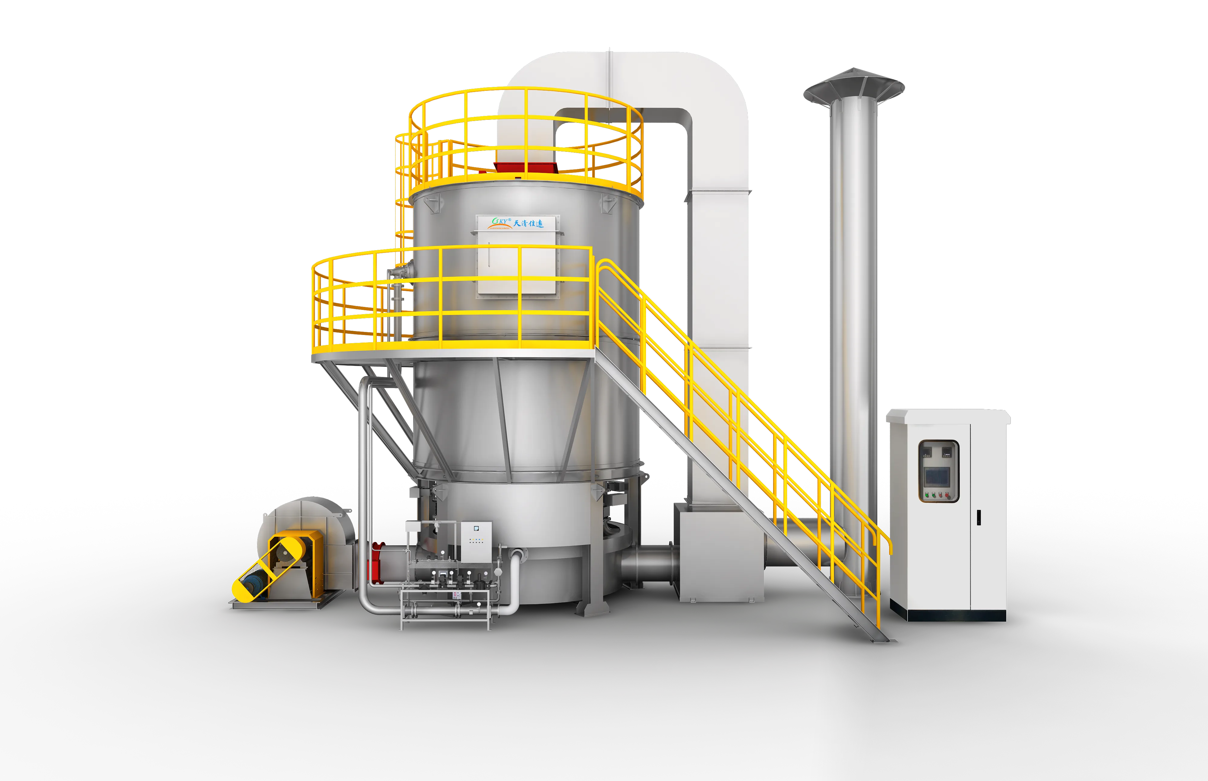
Rotary Regenerative Thermal Oxidizer
A next-generation RTO system utilizing a continuously rotating gas distributor instead of switching valves, providing stable thermal destruction of VOCs with >= 99% purification efficiency, >= 95% thermal recovery, and zero pressure spikes.
Designed around actual process conditions
Designed to eliminate the pressure fluctuations and mechanical wear associated with traditional multi-tower valve-switching RTOs, the FluxFine Rotary RTO features a continuously rotating distribution manifold. By eliminating high-frequency valve cycling, the system ensures uniform gas distribution, exceptionally low noise levels, and minimal maintenance overhead. It represents a highly compact, robust, and continuous thermal oxidation solution for medium-to-high concentration industrial solvent emissions.
Rotary Valve RTO / Valveless RTO / Rotary Bed Thermal Oxidizer / Rotary RTO System
Maintained consistently under nominal VOC load and appropriate combustion temperatures.
Minimizes utility costs, allowing fuel-free self-sustained combustion at concentrations of ~1500-1700 mg/m³.
Continuous gas distribution avoids the hydraulic and acoustic pulses of valve-switching systems.
Operating references and configuration choices
These reference values and modules clarify the scope we evaluate. They are not a substitute for a process-data review or final proposal.
| Engineering reference | Value | How to read it |
|---|---|---|
| Oxidation temperature | 750–850°C | Source operating range; final control setpoint is project-specific. |
| Thermal recovery | ≥95% | Catalog reference under applicable operating conditions. |
| Operating duty | Continuous | Suitable where gas flow and chemistry meet the engineered design basis. |
Typical modules considered
- Rotary regenerative ceramic section
- Oxidation chamber and burner system
- Rotary seal and drive assembly
- Inlet conditioning and flame/pressure protection
- PLC monitoring for temperature, pressure, drive and fan permissives
Project-specific selection notes
- Remove paint mist, sticky aerosol and dust before the regenerator.
- Evaluate seal maintenance and access alongside site footprint.
- Assess concentration excursions and emergency/bypass logic during line start-up, shutdown and recipe changes.
Where rotary RTO fits
Rotary RTO is often considered where a compact continuous regenerative arrangement is useful. It is not automatically the better option for every RTO duty; the selection depends on maintenance preference, gas distribution, layout and control requirements.
- The source material includes rotary-RTO-related examples in coating and optical-film process contexts.
- Final performance and heat recovery require a confirmed airflow, VOC chemistry and heat-balance review.
What we review before specifying Rotary RTO
A product name is a starting point, not a final design. These inputs define pretreatment, materials, controls, equipment size and scope boundaries.
Project data to provide
- VOC species, heat value and LEL assessment
- Normal, minimum and peak airflow/concentration
- Inlet temperature, humidity, dust and condensable material
- Operating schedule, available fuel and heat-reuse demand
- Required emission limit, layout and shutdown window
Typical engineered scope
- Process collection and balancing review
- Pretreatment where dust, mist or corrosive components are present
- Regenerative chambers, combustion system and exhaust stack
- PLC, temperature monitoring, gas-concentration and safety interlocks
- Optional hot-air, hot-water or thermal-oil heat recovery
Safety and controls
- Pre-purge, automatic ignition and flame supervision are selected as part of the combustion package.
- LEL monitoring, emergency exhaust/isolation, fire protection and pressure relief are engineered from the gas risk assessment.
- Chamber temperature, fan status, valve/rotor position and permissives should be visible in the control sequence.
- Final alarm and shutdown setpoints are project-specific; they are not universal website specifications.
How it works
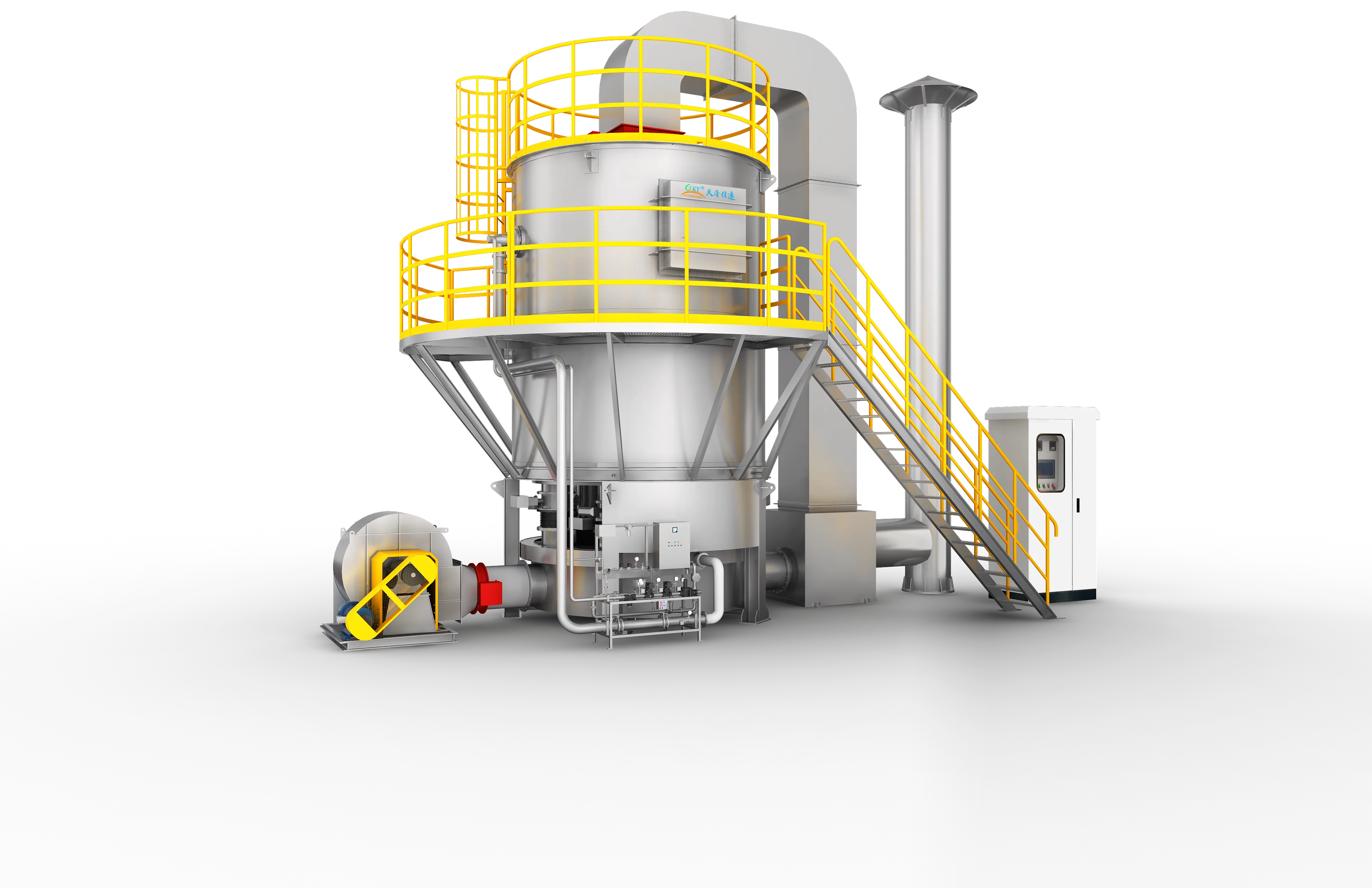
Low-temperature organic exhaust is directed by a rotating distributor continuously into the heating sector of a ceramic regenerator bed. The VOCs absorb stored heat, rising to 750-850°C before entering the central combustion chamber, where they undergo complete thermal oxidation into CO2 and H2O. The purified hot flue gas then flows down through the cooling sector of the regenerator, transferring its thermal energy back to the ceramic media. The continuous rotary motion of the rotor continuously cycles the beds between inlet, purge, and exhaust states, maintaining high thermal recovery (>= 95%) and eliminating flow pulsation.
- 01Inlet process gas collection and pre-filtration to remove trace particulates and liquid droplets.
- 02Uniform gas distribution via the continuously rotating rotor assembly.
- 03Preheating of process air up to 750-850°C as it passes through the ceramic regenerator bed.
- 04Complete thermal oxidation in the combustion chamber at >= 800°C with a residence time of >= 1.0s.
- 05Thermal energy transfer from clean exhaust to the cooling regenerator sector, storing heat for the next cycle.
- 06Continuous rotary purging of the transition chambers to prevent untreated gas leaks during sector switching.
- 07Emission of clean, cooled exhaust gas to the stack up to regulatory compliance.
- Medium-to-high concentration, continuous-flow organic waste gases.
- Production processes sensitive to system pressure fluctuations, such as precision film coating and high-speed printing.
- Plants with restricted installation space requiring a more compact footprint than traditional multi-tower systems.
- VOC abatement in automotive painting, chemical synthesis, pharmaceuticals, and rubber processing.
- Strictly prohibited for treating high-concentration gases near the Lower Explosive Limit (LEL) without prior dilution; an online LEL monitoring system with bypass is required.
- Inlet streams must be thoroughly pre-filtered; high dust or sticky particulate matter will cause clogging in the ceramic regenerator channels.
- Rotor seal and drive mechanism require periodic maintenance to ensure zero-bypass sealing and consistent gas distribution.
- Emergency bypass and flame arrestor systems must be integrated to prevent upstream flashback and safeguard plant operations.
Typical pollutants
- Benzene
- Toluene
- Xylene
- Trimethylbenzene
- Ethyl Acetate
- Butyl Acetate
- Methyl Ethyl Ketone (MEK)
- Cyclohexanone
- Isopropanol
- Ethanol
- Mixed Solvents
Engineering features
- Continuous Gas Distribution: Eliminates switching valves, preventing pressure fluctuations, pipeline vibration, and acoustic noise.
- >= 95% Thermal Efficiency: Highly efficient heat exchange minimizes supplementary fuel demand, supporting self-sustained operation at low VOC concentrations.
- Valveless Rotor Design: Extremely low mechanical failure rate and wear compared to high-frequency pneumatic poppet valves.
- Ultra-High Destruction Efficiency: Consistently achieves VOC destruction efficiency of >= 99% under stable operating conditions.
- Compact Footprint: Integrates the distributor, heat recovery beds, and combustion chamber into a singular, space-optimized package.
Available options
- Skid-mounted integrated package for rapid plug-and-play field installation.
- Secondary waste heat recovery heat exchangers for hot water, steam, or thermal oil generation.
- Dual-fuel burners capable of switching between natural gas, LPG, and light diesel.
- High-concentration LEL auto-dilution safety bypass skid.
Relevant industries
Printing & Laminating
Gravure, flexible packaging, lamination, optical film and continuous web processes.
Coating & Surface Finishing
Industrial paint, UV coating, adhesive, metal finishing and multi-booth surface processes.
Automotive & E-Mobility
OEM parts, e-bike, and industrial spray booth exhaust.
Chemical Industry
Resins, coatings, waterproofing, and specialty chemicals.
Pharmaceutical & Medical
Solvent exhaust from synthesis, coating, and finishing.
Heavy Machinery & Shipbuilding
Large booth coating and high-airflow paint shops.
General technology selection
These answers explain the selection path. Final performance, safety scope and dimensions follow the approved project design.
When is a direct RTO preferable to a concentrator system?
A direct RTO is often evaluated when the inlet VOC load and heat value support efficient thermal oxidation. Large, dilute streams may instead benefit from upstream concentration. The final answer depends on the full airflow and concentration profile.
Can an RTO accept paint mist or dust?
Not without suitable pretreatment. Mist, particulate, sticky material and corrosive components can foul regenerative media or create safety and maintenance risks.
Source basis: 2026 product catalogue and VOCs equipment source. Thermal efficiency and removal figures are project-specific reference values.
Specific product Q&A
How does a valveless rotary RTO prevent VOC leakage?
A Rotary RTO eliminates traditional poppet valves. Instead, it relies on a precision-machined rotary distributor block that rotates continuously over the stator. To prevent raw VOCs from bypassing the destruction chamber through the microscopic gap between the rotor and stator, FluxFine utilizes a continuous pressurized clean-air sealing system. By injecting clean air at a pressure slightly higher than the process exhaust, any leakage is forced back into the dirty process stream to be destroyed, ensuring absolute sealing integrity and >=99% DRE.
What is the pressure drop across a rotary RTO compared to a 3-bed RTO?
A Rotary RTO generally exhibits a lower and significantly more stable pressure drop (typically 2,000-3,000 Pa) compared to a traditional 3-bed RTO. Because a 3-bed RTO requires exhaust to negotiate complex manifolds and multiple abrupt poppet valves, it often incurs higher static resistance. The Rotary RTO's single distribution block provides a smoother, more aerodynamic flow path for the exhaust gas, reducing total fan horsepower requirements.
How does a rotary distribution valve work in an RTO?
The rotary distributor is divided into multiple pie-shaped sectors corresponding to the heat-exchange media beds above it (typically 12 beds). As the distributor slowly rotates (approx. 1 RPM), it sequentially directs incoming dirty exhaust into one group of beds to be pre-heated, routes the hot purified gas exiting the combustion chamber down through a second group of beds to recover heat, and sweeps clean purge air through a third group. This continuous rotation maintains uninterrupted airflow without the pressure spikes caused by slamming poppet valves.
Equipment views
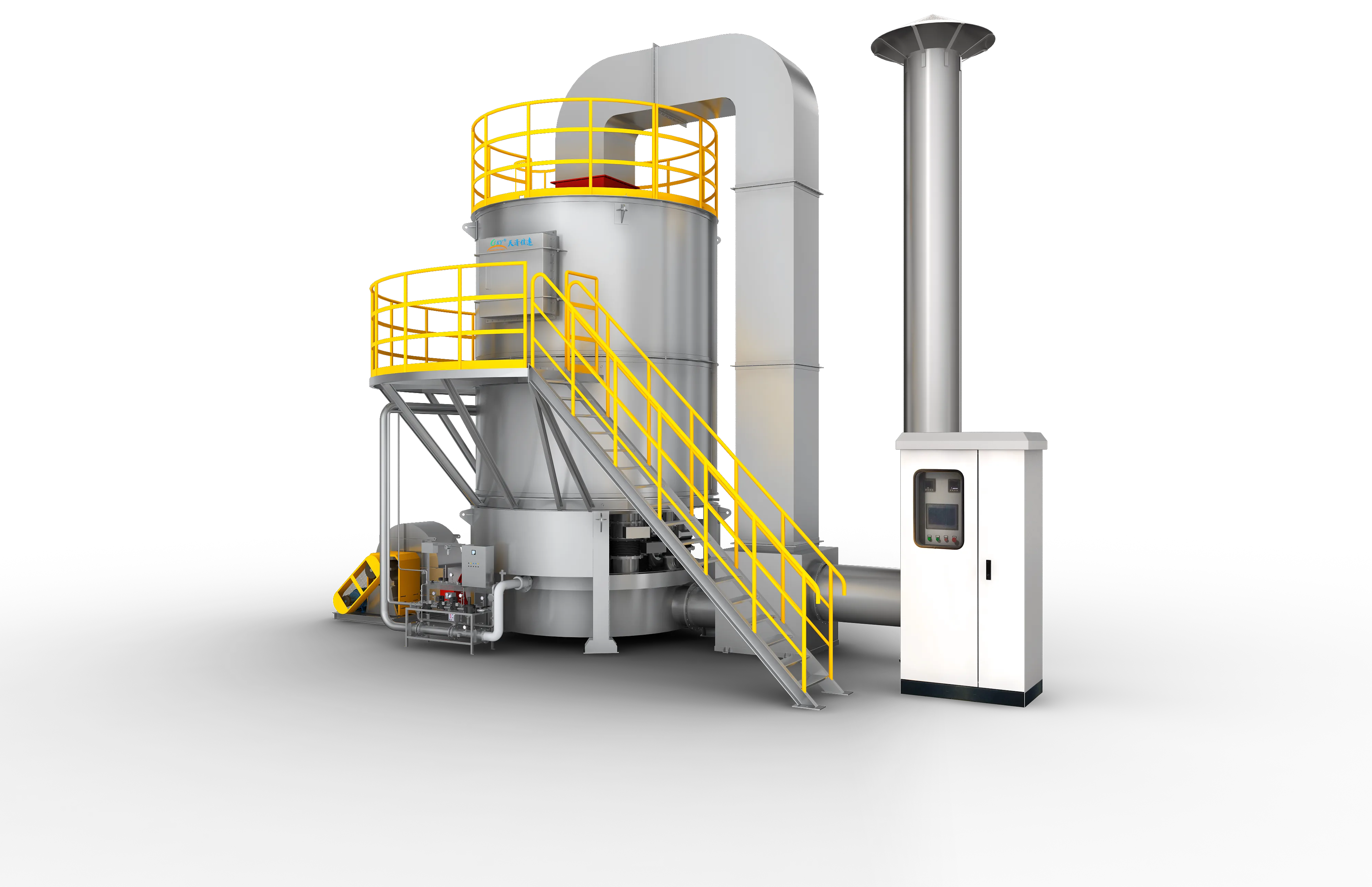
Product images show representative FluxFine configurations. Final dimensions, materials and interfaces follow the approved project design.
Proven Rotary RTO installations
Review documented treatment trains featuring Rotary RTO technology across various industrial processes.
Configure Rotary RTO for your plant
Share measured process data so the engineering team can confirm suitability, pretreatment, equipment size and scope boundaries.
Source basis: Published values are selection references, not a project guarantee.