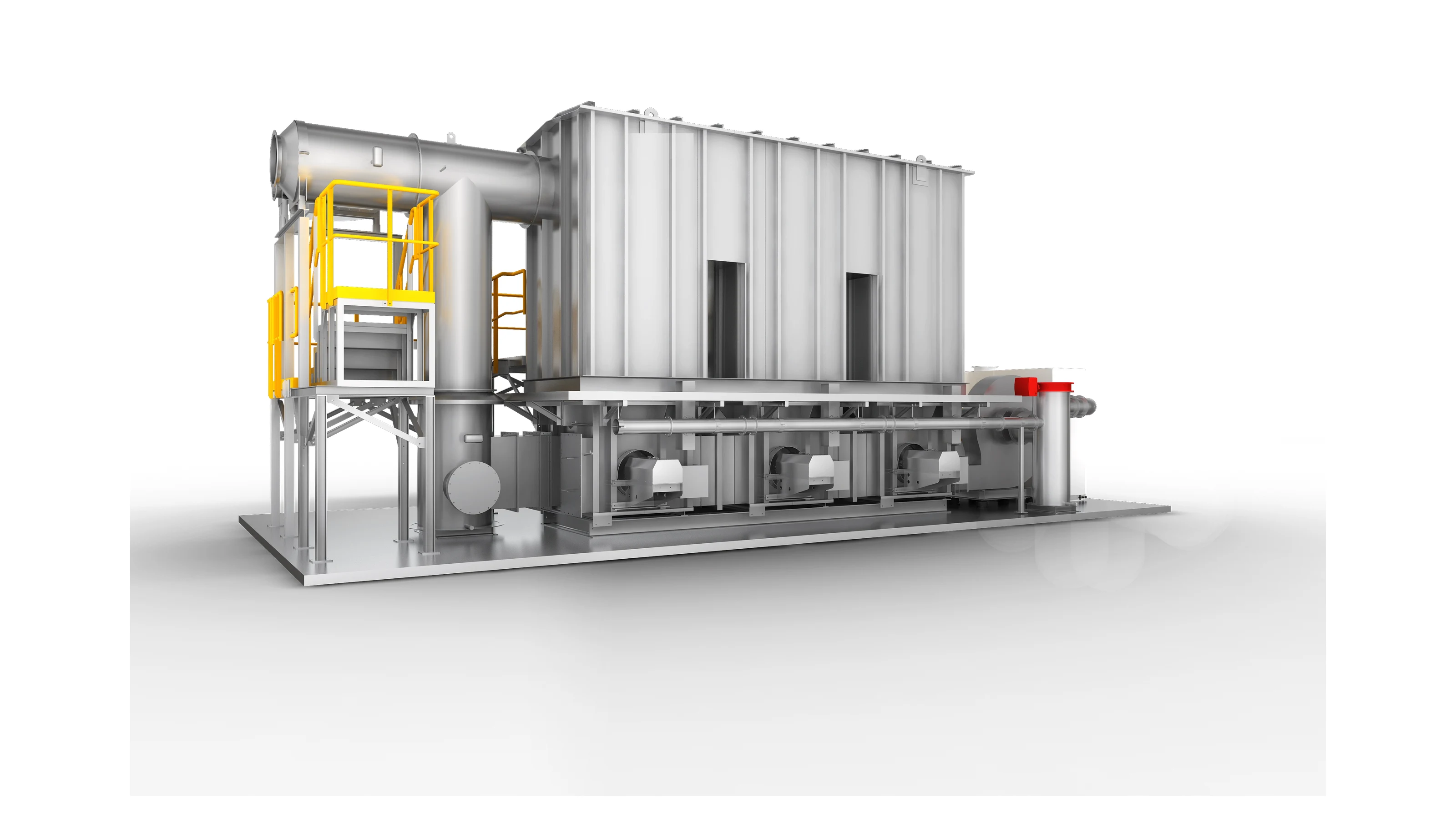
30,000 Nm³/h Automotive Trim Printing & Coating VOCs Abatement System
Hiroca Holdings Ltd. (廣華控股) | Automated Surface Printing, Robotic Spray Coating & High-Temperature Curing Lines
High-Boiling Solvent Challenge Resolved by Direct Three-Bed Regenerative Thermal Oxidation
Hiroca Holdings Ltd. (廣華汽車飾件股份有限公司, TWSE: 1338) is a world-renowned Tier-1 automotive interior and exterior trim manufacturer supplying global automotive leaders including Toyota, Honda, Nissan, Ford, and GAC. Operating specialized surface finishing processes—such as robotic decorative spray painting, water-transfer printing, surface gravure printing, and continuous curing ovens—the manufacturing plant generates complex solvent-laden emissions characterized by high solvent volatility, elevated calorific density, and stringent environmental discharge restrictions.
During initial front-end engineering design, the plant evaluated a conventional Activated Carbon Adsorption-Desorption plus Catalytic Oxidizer (CO) package. However, comprehensive diagnostic audits conducted by FluxFine registered environmental engineers demonstrated that high-boiling solvent constituents—predominantly Toluene (boiling point 110.6°C) and Propylene Glycol Methyl Ether (PGME, boiling point 120.0°C)—exceed safe carbon steam/hot-gas desorption limits (~100°C). This creates chronic residual solvent accumulation, rapid carbon micropore blinding, and catastrophic smoldering fire hazards. Coupled with a heavy inlet concentration of 2,432 mg/Nm³, carbon adsorption media would saturate within hours, causing exorbitant hazardous waste overhead.
FluxFine engineered a high-performance 30,000 Nm³/h (17,650 CFM) Three-Bed Regenerative Thermal Oxidizer (3-Bed RTO) system with Aerodynamic Air Mixing and Closed-Loop Hot Water Waste Heat Recovery. Taking advantage of the solvent mixture's high calorific value (32,277 kJ/kg), the system operates in 100% auto-thermal self-sustaining equilibrium without requiring auxiliary natural gas during regular production. The unit delivers guaranteed VOC destruction removal efficiency (DRE) of ≥98.0% (field operating performance ≥99.2%) and stack emissions of NMHC ≤ 50 mg/Nm³, vastly outperforming client acceptance benchmarks (50–120 ppm / 172–413 mg/Nm³) and exceeding regional Guangdong DB44/2367-2022 standards.
Four Engineering Dilemmas in Automotive Interior Exhaust
Treating combined automotive printing and coating exhaust requires balancing solvent high-boiling chemistry, flammability boundaries, and heavy concentration surges.
High-Boiling Solvent Blend
Exhaust carries Toluene (110.6°C b.p.) and PGME (120.0°C b.p.) alongside Ethyl Acetate, MEK, and Isopropanol. Conventional low-temperature desorption leaves stubborn solvent residue that poisons carbon media.
Elevated Inlet Organic Load
A combined 30,000 Nm³/h stream averaging 2,432 mg/Nm³ rapidly overwhelms carbon beds within hours, rendering batch carbon adsorption economically non-viable and operationally unsustainable.
Desorption Smoldering Risk
Raising carbon desorption above 110°C to release high boilers in the presence of Methyl Ethyl Ketone (MEK) and air triggers severe catalytic oxidation on carbon active sites, risking bed smoldering fires.
LEL Flammability Boundary
The composite Lower Explosive Limit (LEL) is 1.83% by vol (15,762 mg/Nm³ at 25% LEL). Operating at 2,432 mg/Nm³ (~15.4% LEL) demands fail-safe multi-point gas monitoring and fast dilution interlocks.
Comparative Engineering Audit: Activated Carbon + CO vs. Three-Bed RTO
FluxFine conducted a rigorous chemical and thermodynamic comparison evaluating the client's baseline inquiry against direct thermal oxidation.
| Technical Metric / Parameter | Client Baseline (Activated Carbon + CO) | FluxFine Solution (Three-Bed RTO) | Engineering Rationale & Superiority |
|---|---|---|---|
| Process Applicability | Dilute ambient streams (<300 mg/m³) | High-load industrial streams (>2,000 mg/m³) | At 2,432 mg/m³, carbon suffers immediate saturation |
| High-Boiling Solvent Handling | Incomplete desorption of Toluene & PGME; bed fouling | Complete thermal destruction at >760°C to CO₂ & H₂O | Zero residual accumulation; 100% destruction of all species |
| Destruction Efficiency (DRE) | ≥60%–80% (degraded by desorption slip) | ≥98.0% guaranteed (nominal ≥99.2%) | Guarantees stack NMHC ≤ 50 mg/m³ compliance |
| Safety & Fire Hazard Profile | Exothermic carbon hotspotting & smoldering risk | Heavy-duty ceramic media with 25% LEL bypass | Triple LEL safety interlocks with fresh-air dilution |
| Auxiliary Natural Gas Demand | Continuous electric heating for catalytic preheater | Zero gas consumed during steady production | Auto-thermal balance yields surplus -271 kW power |
| Thermal Media Durability | Carbon replacement every 3–6 months; high HW49 cost | Structured cordierite ceramic packing (5–10 yr life) | Eliminates recurring adsorbent purchasing & waste disposal |
| Waste Heat Utilization | None; catalytic discharge vented directly | 65 kW hot water heat exchanger (85°C output) | Preheats printing & coating drying ovens directly |
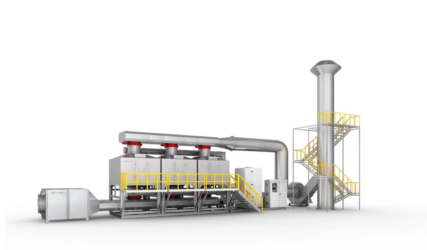
Why Activated Carbon + CO Was Rejected
The client's initial carbon concept required large cooling towers to suppress gas temperatures below 40°C, and multiple dry filter stages to keep dust below 5 mg/m³. Despite these costly auxiliaries, high-boiling Toluene and PGME could never be stripped at 100°C desorption temperatures, resulting in permanent capacity decay and extreme operational downtime. The Three-Bed RTO delivers direct, permanent oxidation without adsorbents.
Key Architectural Innovations in the Hiroca RTO System
Heavy-duty thermal engineering designed to ensure zero transient valve slip, continuous auto-thermal combustion, and circular waste heat recycling.
Three-Bed Regenerative Architecture Eliminates Transient Valve-Switching Slip
Conventional two-bed RTO units suffer from transient valve-switching bypass slip during cycling: when flow direction reverses, untreated VOC-laden gas trapped in the inlet canister is pushed directly into the exhaust stack, producing sudden emission spikes that violate strict continuous emission monitoring (CEMS) caps.
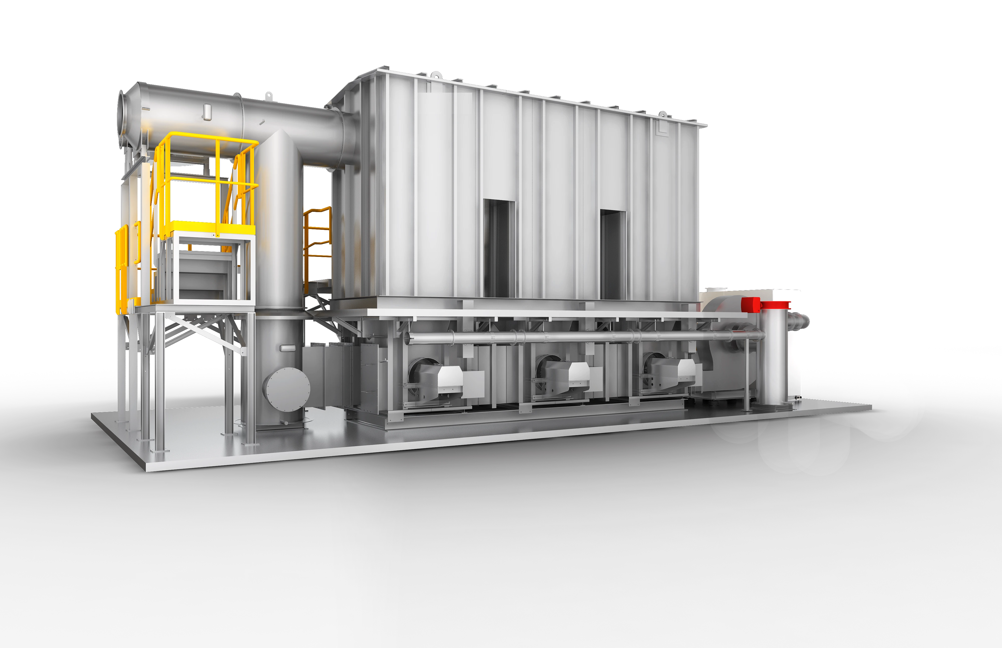
FluxFine engineered a synchronized Three-Bed Regenerative Thermal Oxidizer (3-Bed RTO). At any given moment:Bed A operates in inlet preheating mode;Bed B operates in heat extraction and clean gas discharge mode; and Bed C undergoes high-pressure clean air purging, redirecting residual solvent gases back into the high-temperature combustion chamber. This continuous purge cycle completely prevents raw solvent leakage, ensuring steady-state DRE ≥ 98.0% (nominal ≥99.2%) and stack non-methane hydrocarbons consistently under 50 mg/Nm³.
Multi-Tiered LEL Safety Interlocks and Dynamic Equalization
Handling high solvent loadings averaging 2,432 mg/Nm³ (~15.4% LEL) demands fail-safe flammability defense. FluxFine engineered a complete safety matrix incorporating upstream aerodynamic mixing, multi-stage detection, and redundant physical barriers.
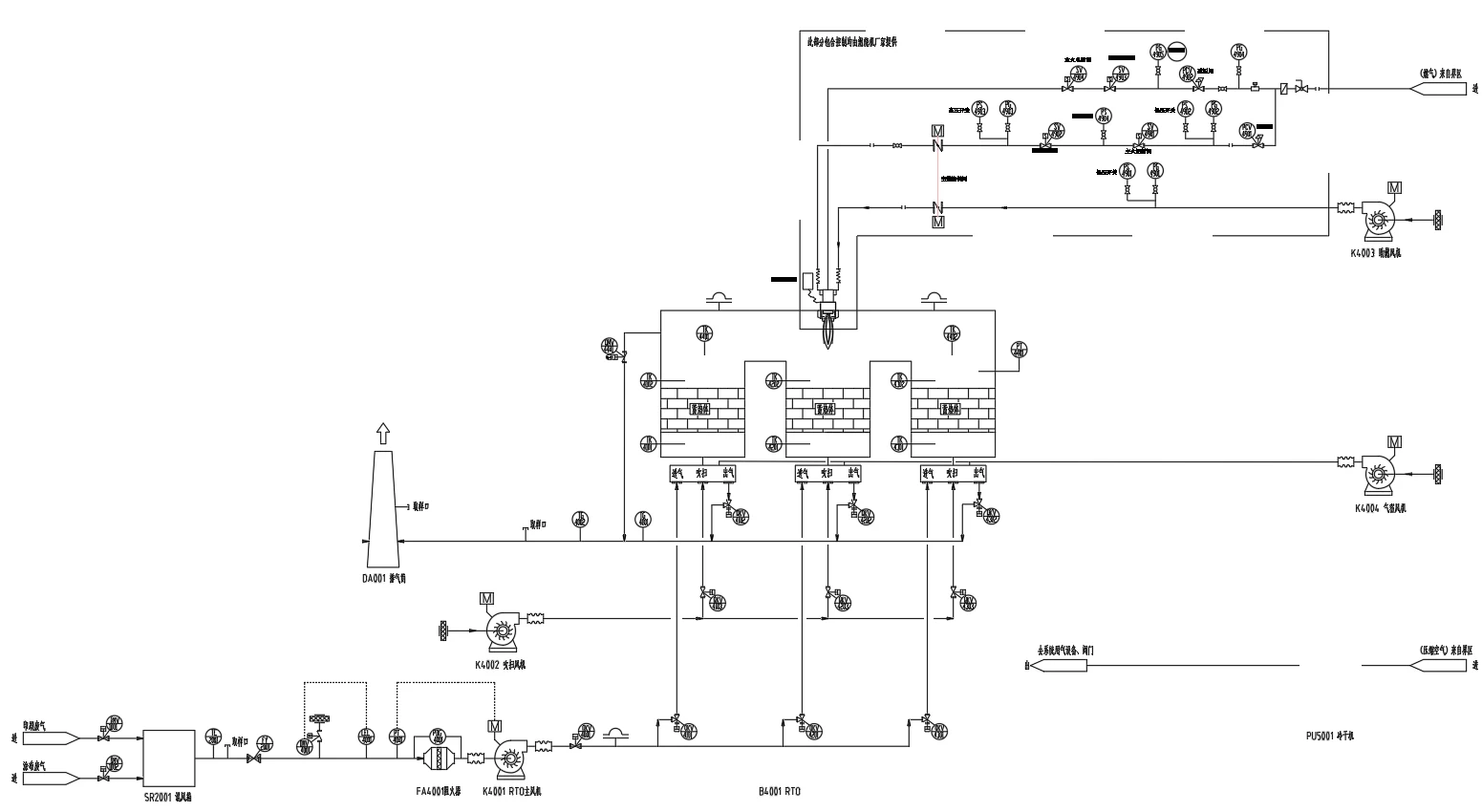
As detailed in the P&ID layout, the process incorporates:(1) Equalization mixing chamber (SR2001) to homogenize cyclical solvent concentrations from the printing (24,000 m³/h) and coating (6,000 m³/h) lines;(2) Heavy-duty metal mesh prefilter & flame arrester (FA4001) to arrest particulates and prevent flame propagation;(3) Dual fast-response optical/infrared LEL sensors linked to an emergency fresh air dilution damper. If VOC concentrations exceed 20% LEL, fresh air modulates to dilute the stream; at 25% LEL, automatic emergency bypass activates within 0.8 seconds to isolate the combustion unit.
Auto-Thermal Self-Sustaining Operation at 2,432 mg/Nm³ (-271 kW Net Heat)
The composite solvent blend (Ethyl Acetate, Isopropanol, Toluene, MEK, PGME) exhibits a rich heating value averaging 32,277 kJ/kg (up to 33,000 kJ/kg). In standard RTO systems equipped with structured cordierite ceramic packing, the self-sustaining auto-thermal threshold occurs at approximately 2,000 mg/Nm³.
Operating under Hiroca's normal baseline conditions of 2,432 mg/Nm³, the heat released during thermal oxidation inside the 794°C combustion chamber substantially exceeds the thermal loss of the system. Thermodynamic mass-energy balance reveals a net surplus heating power of -271 kW. Consequently, once preheated during morning startup, the natural gas modulating burner throttles back to low-fire pilot mode, consuming zero auxiliary fuel during full-shift production.
Thermodynamic Auto-Thermal Balance Matrix
- Design Airflow
- 30,000 Nm³/h (17,650 CFM)
- Composite VOC Calorific Value
- 32,277 – 33,000 kJ/kg
- Combustion Chamber Temperature
- 794°C (760°C – 820°C Range)
- Ceramic Thermal Energy Recovery
- ≥95% TER
- Auto-Thermal Equilibrium Threshold
- ≥2,000 mg/Nm³
- Operating Auxiliary Heating Power
- -271 kW (Surplus Heat)
Secondary Heat Recovery Architecture
65 kW Hot Water Secondary Recovery Loop Feeds Facility Drying Ovens
In standard thermal oxidizers without secondary heat integration, clean oxidized flue gas is vented to the atmosphere at elevated temperatures, wasting substantial high-grade thermal enthalpy.
FluxFine integrated a secondary SUS316L shell-and-tube hot water heat exchanger downstream of the ceramic heat storage beds. The system continuously captures 65 kW of thermal energy, circulating pressurized hot water at 85°C directly into the fresh-air heating coils of Hiroca's printing and coating curing ovens. By displacing utility steam and electric heating demand in the drying tunnels, this circular heat integration delivers substantial operational energy reductions.
Guaranteed Environmental & Thermal Performance
Verified engineering parameters under full-load production at Hiroca Automotive Trim.
| Engineering Parameter | Client Specification / Acceptance | FluxFine Design Value | Operating Field Performance |
|---|---|---|---|
| Total Treated Exhaust Airflow | 30,000 m³/h (Printing 24k + Coating 6k) | 30,000 Nm³/h (17,650 CFM) | 30,000 Nm³/h continuous |
| VOC Destruction Removal (DRE) | >90.0% Removal Rate | ≥98.0% Guaranteed | ≥99.2% Measured |
| Stack Exhaust Concentration | 50 – 120 ppm (172 – 413 mg/Nm³) | NMHC ≤ 50 mg/Nm³ | NMHC ≤ 28 mg/Nm³ |
| Combustion Chamber Temperature | ≥760°C Minimum | 794°C Operating Point | 790°C – 805°C Stable |
| Auxiliary Natural Gas Fuel Rate | Standard fuel consumption allowed | Zero Gas (Self-Sustaining) | 100% Autothermal (-271 kW) |
| Secondary Waste Heat Recovery | None required | 65 kW Hot Water Loop | 65 kW @ 85°C delivered |
| Poppet Valve Switching Speed | ≤2.0 seconds | ≤1.0 second stroke | 0.75s pneumatically cushioned |
Hiroca 30,000 Nm³/h RTO Treatment Flow Train
Engineered flow path from multi-line extraction to high-altitude compliant discharge.
Source Collection
Capture from 24,000 m³/h printing line and 6,000 m³/h coating tunnel under negative static pressure.
Equalization & Filter
Aerodynamic mixing chamber balances concentration surges; SUS304 wire-mesh arrests paint mist droplets.
LEL Safety Interlocks
Multi-point continuous LEL gas sensors guard inlet; automatic high-speed dilution damper triggers at 20% LEL.
3-Bed RTO Oxidation
794°C ceramic honeycomb thermal bed achieves ≥98% DRE with zero auxiliary fuel under auto-thermal equilibrium.
Heat Recovery & Stack
65 kW hot water heat exchanger recycles 85°C water to curing ovens; clean gas discharges at NMHC ≤ 50 mg/m³.
Equipment in This Project
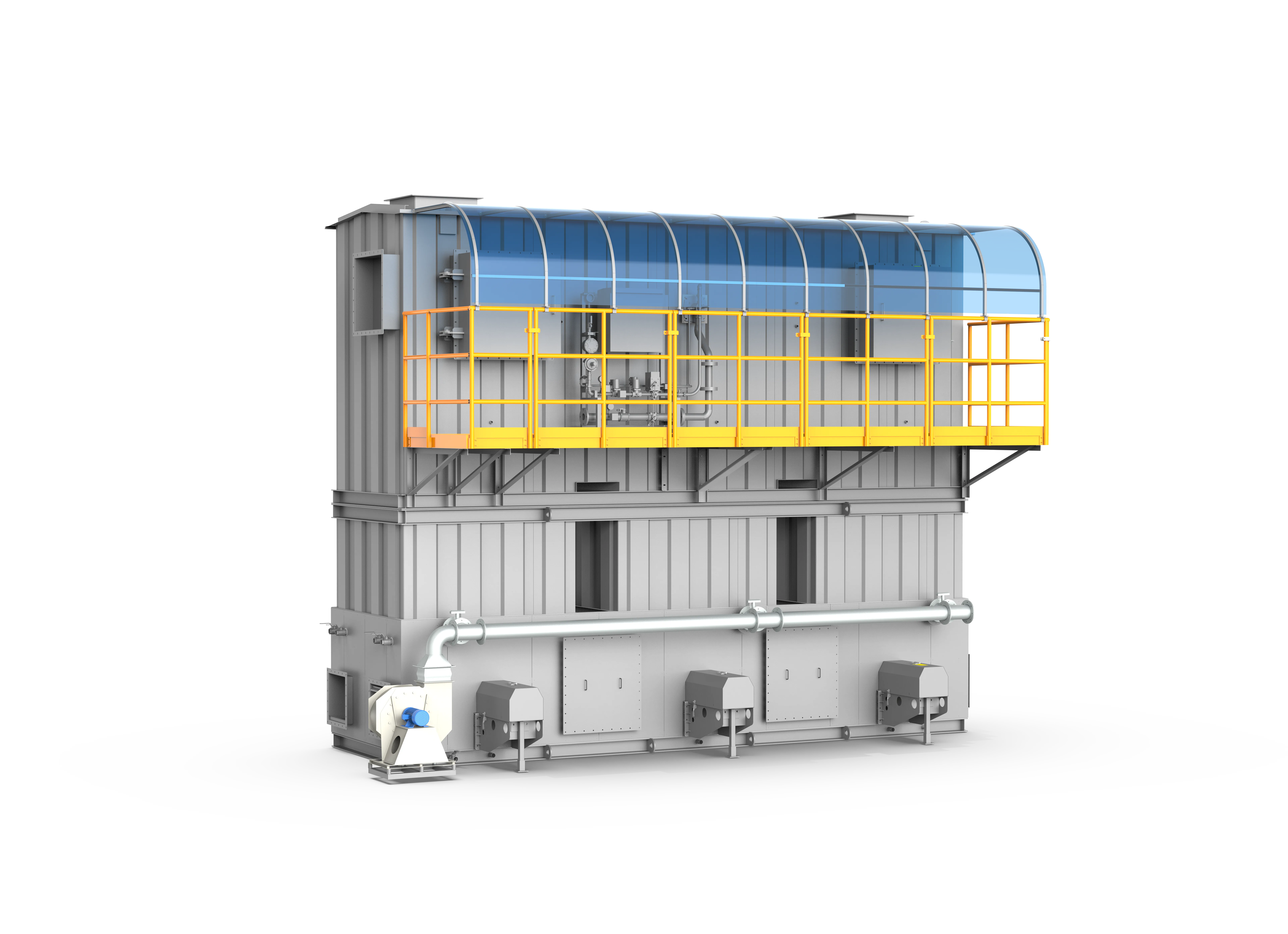
Three-Tower RTO
A premier-grade industrial VOC thermal abatement system that achieves >=99% VOC destruction efficiency and >=95% thermal energy recovery through a classic three-bed alternating heat-exchange and purge process.
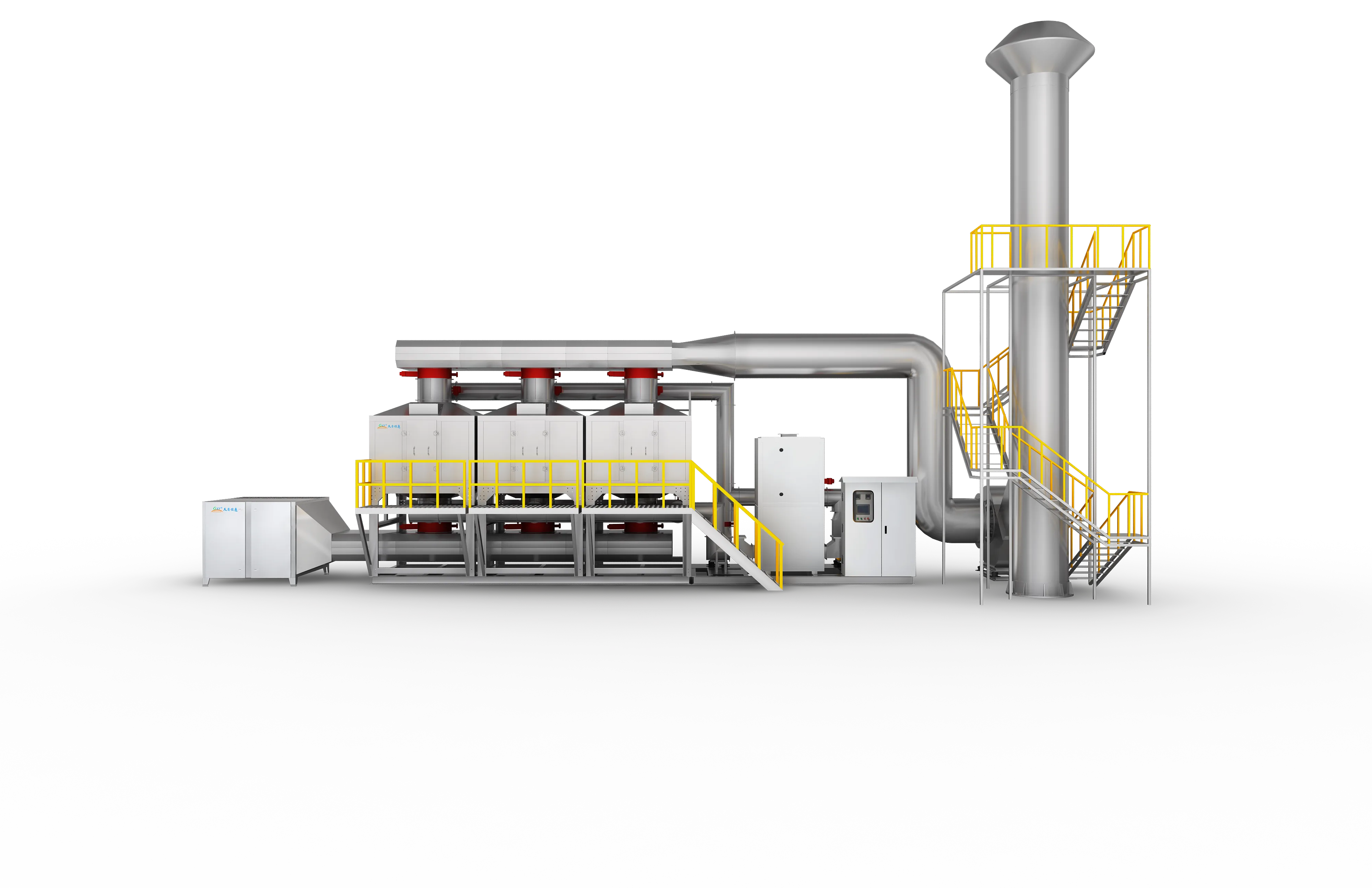
Carbon + CO
An exceptionally economical VOC abatement package integrating multi-bed activated carbon adsorption with hot-air thermal regeneration and low-temperature catalytic oxidation (CO) for small-scale, intermittent emissions.
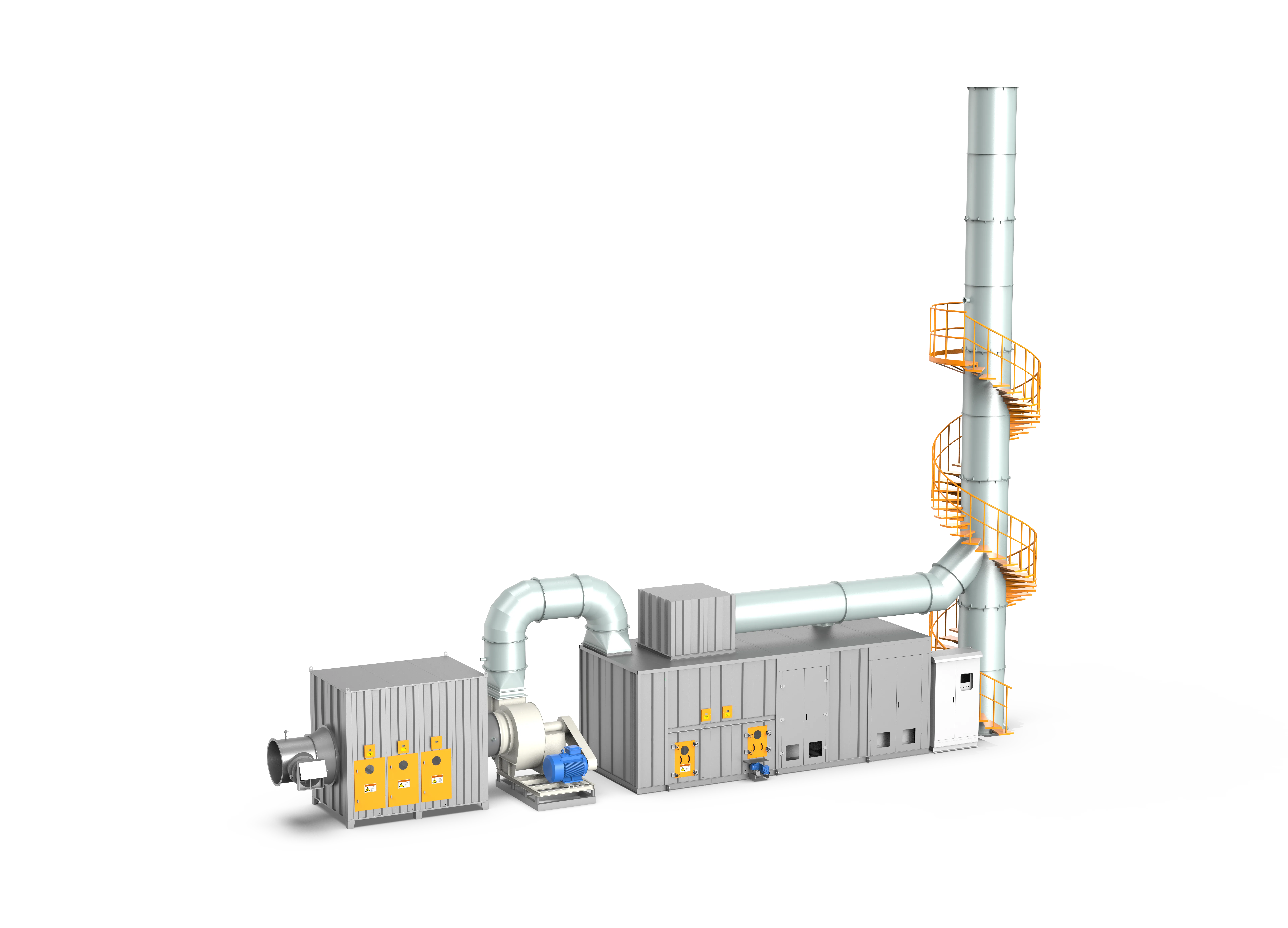
RCO
Ceramic heat regeneration combined with catalytic oxidation for compatible VOC streams requiring continuous, energy-conscious treatment.
Evaluate Regenerative Thermal Oxidation for Your Automotive Coating Lines
Consult with FluxFine environmental engineers to model airflow kinetics, solvent calorific balances, and custom waste heat recovery loops for guaranteed environmental compliance.